Application method of hard carbon negative electrode material in sodium-ion battery
The technology of a sodium ion battery and its application method, which is applied in the field of sodium ion batteries, can solve the problems of ignoring the influence of the formation of the interface film on the electrochemical performance and the low electrochemical performance of the battery, so as to achieve the advantages of electric charge transmission, excellent rate performance, and small battery capacity. Effect of Polarization Voltage
- Summary
- Abstract
- Description
- Claims
- Application Information
AI Technical Summary
Problems solved by technology
Method used
Image
Examples
Embodiment 1
[0036] The application method of hard carbon negative electrode material on sodium ion battery, this application method comprises:
[0037] (1) Negative plate preparation: mix hard carbon material, acetylene black, binder sodium alginate (SA) and SBR in a mass ratio of 8:1:1, then add water, ball mill into slurry, and coat on On copper foil, after coating, vacuum-dry at 60°C, roll and press after drying, and cut into negative electrode sheets, the mass of active material per unit area is 1.5-2.0mg cm -2 .
[0038] (2) Preparation of positive electrode sheet: mix the active material, conductive agent, and binder at a mass ratio of 8:1:1, then add nitrogen-methylpyrrolidone (NMP), ball-mill it into a slurry, and coat it on aluminum foil. After coating, dry it in vacuum at 80°C, roll it after drying, and cut it into pole pieces. The mass of active material per unit area is 4.0-5.0 mg cm -2 .
[0039] (3) Battery assembly: including the positive electrode sheet (Na sheet and Na...
experiment example 1
[0047] Electrochemical performance and mechanism test
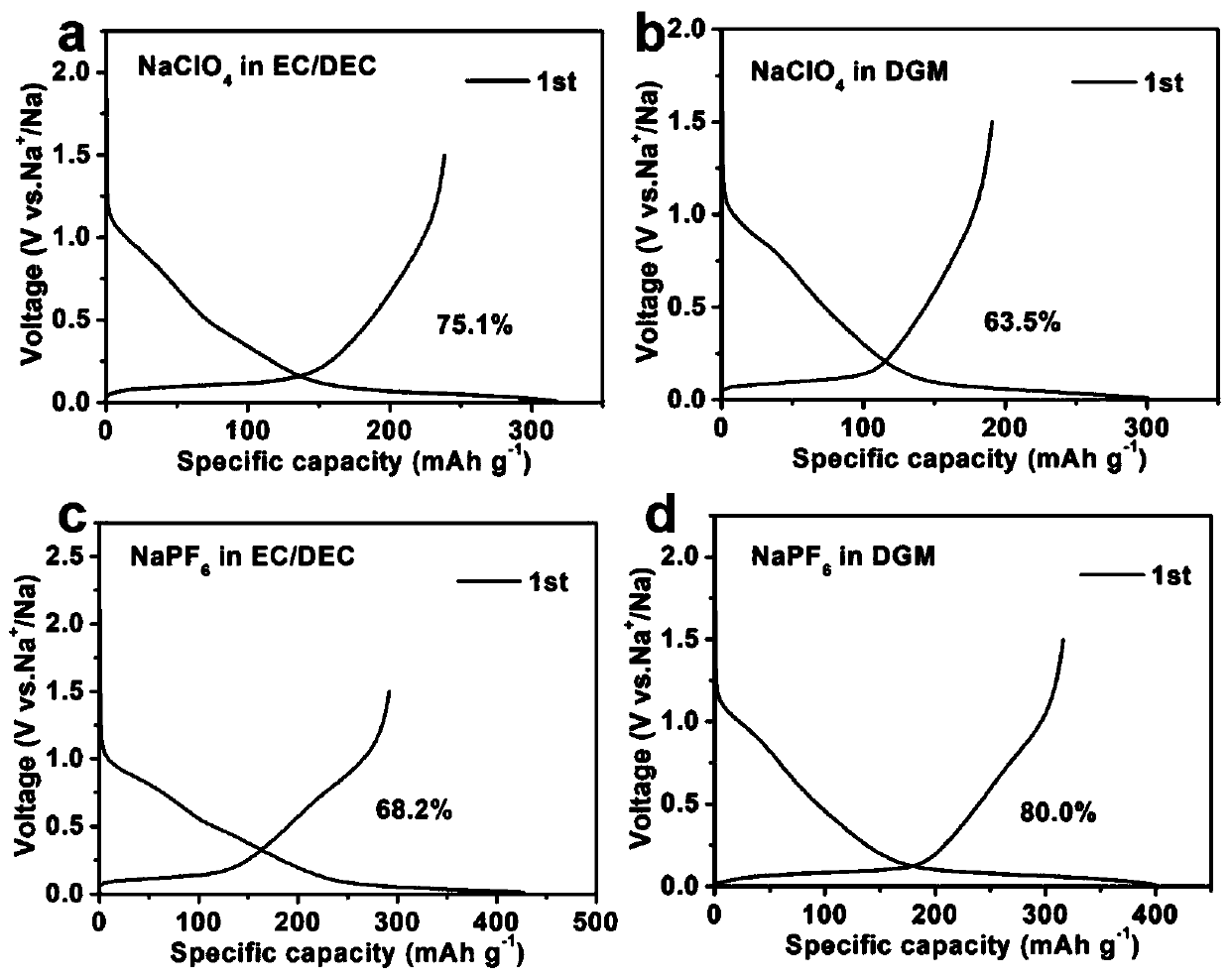
[0048] Example 1 and Comparative Examples 1-3 were tested for the first-cycle coulombic efficiency, as can be seen from the first-cycle coulombic efficiency, the hard carbon material in NaPF 6 -The first effect in DGM electrolyte is higher than that in NaClO 4 -EC / DEC electrolyte, NaClO 4 -DGM electrolyte and NaPF 6 -EC / DEC electrolyte.
[0049] figure 2 It is the experimental example 1 of the present invention in NaPF 6 -Charge-discharge curve and in-situ XRD diffraction pattern diagram of the electrochemical reaction mechanism in the DGM electrolyte; a is the charge-discharge curve, b is the in-situ XRD diffraction pattern diagram, it can be seen from the figure that there is no diffraction during the discharge process The change of the peak indicates that only the adsorption of sodium ions has occurred. With the gradual decrease of the potential, there is a new peak Na x The formation of C indicates that the har...
experiment example 2
[0051] Formation mechanism and control of SEI film
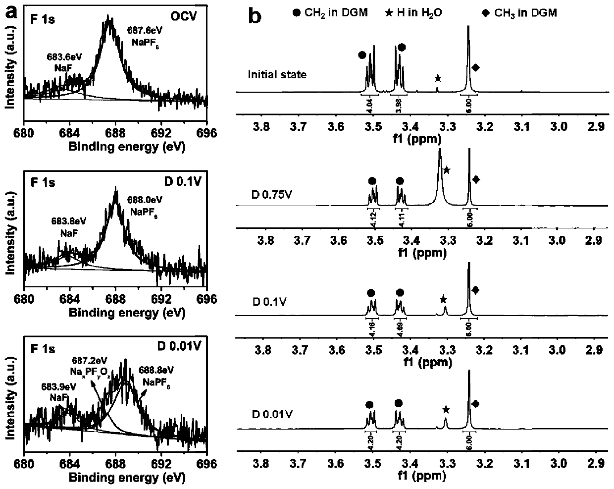
[0052] From the NMR spectra, it can be seen that image 3 a is the change of F1s energy spectrum during the discharge process, indicating that NaPF under OCV 6 React with water to produce NaF, when discharged to 0.01V, NaPF 6 Decomposition produces Na x PF y o z . image 3 b is during discharge 1 The change of H spectrum, it can be seen that in the whole discharge process, DGM has not changed, and at the same time and figure 1 Corresponding to the high first-cycle Coulombic efficiency, we found that by adjusting the concentration of the electrolyte, the thickness of the SEI film can be controlled, such as Figure 4 As shown, as the electrolyte concentration increases, the SEI film becomes thicker and thicker.
PUM
| Property | Measurement | Unit |
|---|---|---|
| specific surface area | aaaaa | aaaaa |
Abstract
Description
Claims
Application Information
 - R&D
- Intellectual Property
- Life Sciences
- Materials
- Tech Scout
- Unparalleled Data Quality
- Higher Quality Content
- 60% Fewer Hallucinations
Browse by: Latest US Patents, China's latest patents, Technical Efficacy Thesaurus, Application Domain, Technology Topic, Popular Technical Reports.
© 2025 PatSnap. All rights reserved.Legal|Privacy policy|Modern Slavery Act Transparency Statement|Sitemap|About US| Contact US: help@patsnap.com


