A capacitively coupled plasma discharge device

A plasma and discharge device technology, applied in the field of plasma discharge devices, can solve problems such as poor plasma axial symmetry, and achieve the effect of ensuring axial symmetry

Active Publication Date: 2021-05-04
DALIAN UNIV OF TECH
View PDF19 Cites 0 Cited by
  • Summary
  • Abstract
  • Description
  • Claims
  • Application Information

AI Technical Summary

Problems solved by technology

However, in the commonly used laboratory parallel plate plasma source, due to the use of various diagnostic methods, the plasma will diffuse to the side wall of the grounded chamber, and the side wall also becomes a part of the ground electrode, resulting in the area of ​​the ground electrode being much larger than that of the driving electrode Area, forming a DC negative bias on the surface of the driving electrode, resulting in poor axial symmetry of the plasma, so it is difficult to compare with computer simulation results (most one-dimensional models can only simulate axially symmetric plasma structures)

Method used


Image

  • A capacitively coupled plasma discharge device
  • A capacitively coupled plasma discharge device
  • A capacitively coupled plasma discharge device

Examples


Embodiment Construction

[0020]Next, the technical solutions in the embodiments of the present invention will be apparent from the embodiment of the present invention, and it is clearly described, and it is understood that the described embodiments are merely embodiments of the present invention, not all of the embodiments. Based on the embodiments of the present invention, there are all other embodiments obtained without making creative labor without making creative labor premises.

[0021]It is an object of the present invention to provide a plasma vacuum discharge system to expand the adjustment range of self-bias.

[0022]In order to make the above objects, features, and advantages of the present invention, the present invention will be further described in detail below with reference to the accompanying drawings and specific embodiments.

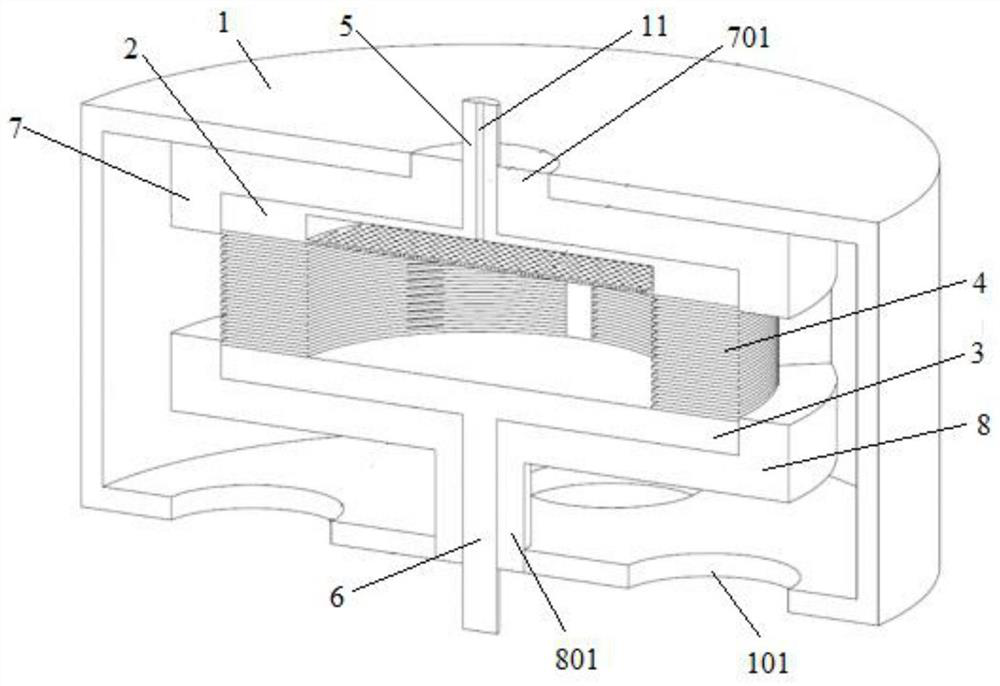
[0023]figure 1 A cross-sectional view of an embodiment of a capacitive coupling plasma discharge device of the present invention.

[0024]Seefigure 1 This capacitive coupling pl...


PUM


Abstract

The invention discloses a capacitive coupling plasma discharge device. The plasma discharge device comprises: a vacuum chamber, an upper plate electrode and a lower plate electrode located in the vacuum chamber, and insulating rings stacked between the upper plate electrode and the lower plate electrode; each insulating ring is connected to the adjacent There is a gap between the insulating rings; the uppermost insulating ring in the stacked insulating rings is in contact with the lower surface of the upper plate electrode, and the lowermost insulating ring is in contact with the upper surface of the lower plate electrode; the upper plate electrode is connected with the first The discharge drive rod, the first discharge drive rod extends outside the vacuum chamber; the lower plate electrode is connected with the second discharge drive rod, and the second discharge drive rod extends outside the vacuum chamber. Adopting the plasma discharge device of the invention can ensure the axial symmetry of the plasma during the experiment.

Description

Technical field[0001]The present invention relates to the field of plasma discharge, and more particularly to a capacitive coupling plasma discharge device.Background technique[0002]Contentively coupled plasma (CCP) sources can generate large area, uniform plasma characteristics due to its simplicity, and can be widely used in material etching and deposition industries. The capacitive coupling (parallel plate electrode structure) plasma source is a closed system, which has no diagnostic (increasing the diagnostic window to destroy the state of the plasma, affecting the material etching or deposition quality). In order to optimize plasma etching or deposition processes, a multi-directional experimental diagnosis and computer simulation study on plasma sources are required. This requires reasonable design of the laboratory medium ionic source. In addition, if you want to perform one-dimensional computer simulation on the actual plasma source, the plasma between the parallel plates is ...

Claims


Application Information

Patent Timeline
Patent Type & Authority Patents(China)
IPC IPC(8): H05H1/46
CPCH05H1/46
Inventor 刘永新王祥宇苏子轩王友年
Owner DALIAN UNIV OF TECH
Why Eureka
Try Eureka