Optical imaging system, imaging method and microscope

A technology of optical imaging system and beam expander system, which is applied in the field of imaging method, microscope and optical imaging system, and can solve the complicated and complicated adjustment process of the microscopic system.

Pending Publication Date: 2020-08-25
SHENZHEN UNIV
View PDF7 Cites 0 Cited by
  • Summary
  • Abstract
  • Description
  • Claims
  • Application Information

AI Technical Summary

Problems solved by technology

[0004] The present invention provides an optical imaging system, an imaging method and a microscope, aiming to solve the problem that the microsystem in the prior art cannot perform continuous frequency shift and phase shift, and needs to replace the lens many times, so that the adjustment process of the microsystem is cumbersome and complicated The problem

Method used


Image

  • Optical imaging system, imaging method and microscope
  • Optical imaging system, imaging method and microscope
  • Optical imaging system, imaging method and microscope

Examples


Embodiment Construction

[0041] The following will clearly and completely describe the technical solutions in the embodiments of the present invention with reference to the accompanying drawings in the embodiments of the present invention. Obviously, the described embodiments are only part of the embodiments of the present invention, not all of them. Based on the embodiments of the present invention, all other embodiments obtained by persons of ordinary skill in the art without creative efforts fall within the protection scope of the present invention.

[0042] It should be noted that all directional indications (such as up, down, left, right, front, back...) in the embodiments of the present invention are only used to explain the relationship between the components in a certain posture (as shown in the accompanying drawings). Relative positional relationship, movement conditions, etc., if the specific posture changes, the directional indication will also change accordingly.

[0043] In addition, in t...


PUM


Abstract

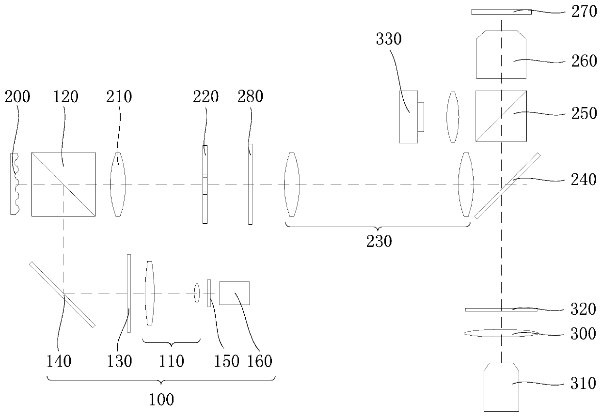
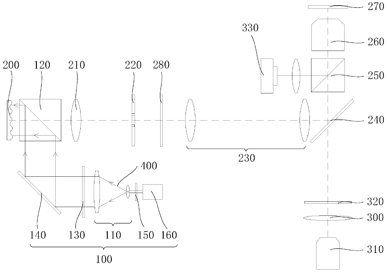
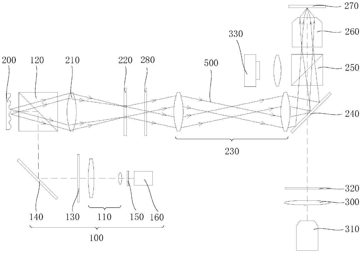
The invention discloses an optical imaging system, an imaging method and a microscope. The optical image capturing system includes of a light source module and a phase grating, wherein first light emitted by the light source module is transmitted to the phase grating, the phase grating reflects the first light into the second light along the second light path direction, a sample on the object placing table emits third light after receiving the second light, and the optical imaging system sequentially comprises a third lens group and a first camera along the transmission direction of the thirdlight. The optical imaging system is advantaged in that through the phase grating, the microscopic system can perform continuous frequency shift and phase shift, and problems that in the prior art, the microscopic system cannot perform continuous frequency shift and phase shift, a lens needs to be replaced for multiple times, and thus the adjustment process of the microscopic system is tedious andcomplex are solved.

Description

technical field [0001] The invention relates to the technical field of optical imaging, in particular to an optical imaging system, an imaging method and a microscope. Background technique [0002] A microscope is an optical instrument composed of a combination of one or more lenses. It is mainly used to observe tiny objects, especially the observation of subcellular structures is one of the major needs in the field of life sciences. In the existing technology , the subcellular structure is mainly imaged by super-resolution microscopic imaging technology, among which structured light illumination fluorescence microscopy (Structure Illumination Microscopy, SIM) is a method of obtaining a microscopic image of a sample by irradiating the surface of the sample with specific structured light. [0003] At present, the structured light used for sample irradiation is mainly generated by light transmission gratings, among which spatial light modulator (spatial light modulator, SLM) a...

Claims


Application Information

Patent Timeline
IPC IPC(8): G02B21/00G02B21/36
CPCG02B21/0032G02B21/0052G02B21/0068G02B21/361
Inventor 孟繁斐杨爱萍杜路平袁小聪
Owner SHENZHEN UNIV
Why Eureka
Try Eureka