Camera damage detection method and system based on average optical flow gradient

A detection method and optical flow technology, which is applied in image data processing, complex mathematical operations, instruments, etc., can solve problems that cannot be comprehensive, sensors cannot detect occlusion, movement, and many objects, and achieve the effect of reducing labor costs

Pending Publication Date: 2022-04-19
FUDAN UNIV
View PDF3 Cites 1 Cited by
  • Summary
  • Abstract
  • Description
  • Claims
  • Application Information

AI Technical Summary

Problems solved by technology

This method can identify the two situations in which the camera is moved or blocked, but it is necessary to determine the normal background data set of the camera picture in order to compare it with it to obtain the change difference
This increases the cost of labeling the normal background set, and the method is not very autonomous
At the same time, this method only uses the grayscale information of the camera picture, and the robustness of the method is poor in the face of complex picture information and large picture noise such as damaged forms.
[0005] In summary, the existing camera protection devices will generate additional material costs, and the sensors used to detect touch and vibration cannot detect occlusion, movement, etc., and vice versa. Some methods of detecting occlusion, movement, etc. are different methods to deal with different forms of damage, and the abnormal judgment of camera damage is more complicated and cannot be exhaustive.
The method of using the background difference method to extract the foreground and background of the camera picture for comparison only compares the grayscale image of the current frame of the video with the grayscale image of the normal background set. This may be because there are many objects (people or cars) in the picture, occupying The main scene of the picture, which will also lead to a large difference in the grayscale image of the picture, and the robustness of the algorithm is poor

Method used


Image

  • Camera damage detection method and system based on average optical flow gradient
  • Camera damage detection method and system based on average optical flow gradient
  • Camera damage detection method and system based on average optical flow gradient

Examples


Embodiment 1

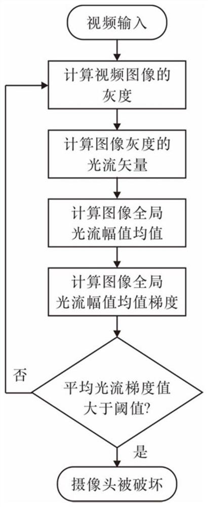
[0067] A camera failure detection method based on the average optical flow gradient, including the following steps:

[0068] S1, the camera captures the video image, acquires the current frame image and the previous frame image;

[0069] Generally speaking, when the camera works, it will collect a continuous frame sequence, that is, video, you can set the sampling interval as needed, such as 0.1 seconds, or directly use the continuous frame image sequence collected by the camera to obtain two adjacent frame images, wherein the current frame image is the frame image collected at t moment, and the previous frame image is the frame image collected at -1 moment.

[0070] S2, grayscale processing, to obtain the gray map of the current frame image and the gray map of the previous frame image;

[0071] In the present embodiment, the use of three primary colors (red, green, blue) and other proportions of each pixel of the image superimposed together to calculate the gray value, using the ...

other Embodiment approach

[0074] In other embodiments, the method of weighted averaging may also be used, each channel is set with different weights, calculating the grayscale value.

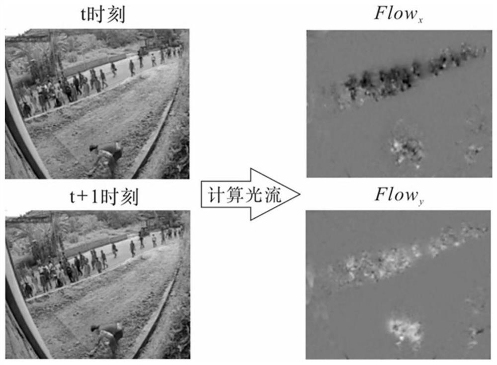
[0075] S3, enter the grayscale map of the current frame image and the grayscale plot of the previous frame image, calculate the dense optical flow field between the two frames of the image, and each point in the optical flow field is the displacement of the corresponding pixel point in the x and y directions;

[0076] The optical flow of the picture is defined as the movement mode of the object in the image between successive frames, which may be caused by the movement of the object or the camera, it can be expressed as a displacement vector in a two-dimensional vector field, representing the movement of pixels from one frame to another, also known as the optical flow vector. At present, there are many algorithms for optical flow calculation, according to the design needs of this application, choose to use the Farneback meth...

Embodiment 2

[0129] The present application also protects a camera damage detection system based on an average optical flow gradient, comprising:

[0130] Data acquisition module, connected with the camera, the camera acquires video images, and the data acquisition module acquires the current frame image and the previous frame image;

[0131] Pre-processing module, the image is grayscaled, and the grayscale diagram of the current frame image and the grayscale diagram of the previous frame image are obtained;

[0132] Optical flow field calculation module, taking the grayscale diagram of the current frame image and the grayscale diagram of the previous frame image as input, calculates the dense optical flow field between the two frames of the image, and each point in the optical flow field is the displacement of the corresponding pixel point in the x and y directions;

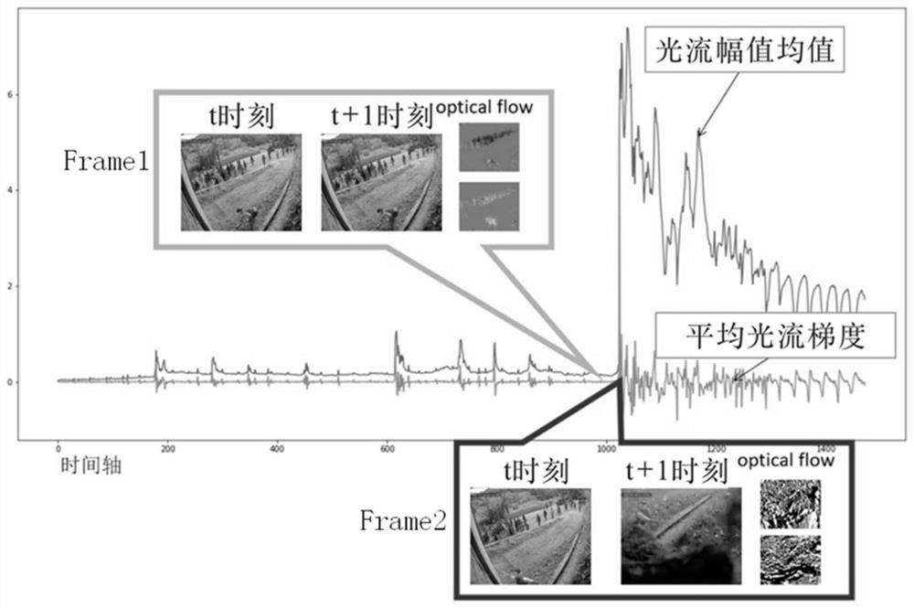
[0133] Optical Flow Amplitude Mean Calculation Module, based on dense optical flow field, calculate the mean optical flow ampl...


PUM


Abstract

The invention relates to a camera damage detection method and system based on an average optical flow gradient. The method comprises the following steps: acquiring a current frame image and a previous frame image; obtaining a grey-scale map of the current frame image and a grey-scale map of the previous frame image; the gray-scale map of the current frame image and the gray-scale map of the previous frame image are input, a dense optical flow field between the two frames of images is calculated, and each point in the optical flow field is the displacement of a corresponding pixel point in the x direction and the y direction; calculating an optical flow amplitude mean value based on the dense optical flow field; and calculating a gradient of the light flow amplitude mean value based on the light flow amplitude mean value, recording the gradient as an average light flow gradient, and if the average light flow gradient meets a preset judgment condition, considering that the camera is damaged. Compared with the prior art, the automatic detection of camera damage is mainly realized by detecting the violent change of a camera picture, the change of the camera picture is described by taking the average optical flow gradient as a characteristic, and whether the camera is damaged is judged by judging whether the change of the current optical flow characteristic exceeds a set threshold value or not.

Description

Technical field [0001] The present invention relates to the field of camera destruction detection, in particular to a camera failure detection method and system based on an average optical flow gradient. Background [0002] With the development and progress of the country, the application of social security monitoring measures is becoming more and more extensive. Surveillance cameras are an important means of security, and surveillance cameras are generally provided in banks, schools, military camp boundaries and other places. When the camera collects video information, if it is obscured by debris or maliciously damaged, it cannot capture the actual situation at the scene, which may cause security risks. The traditional manual guard surveillance screen can check the working status of the camera in a small number of cameras, but if the number of cameras is huge, it is difficult for the manual guard to find out in real time whether the camera is destroyed. [0003] The existing de...

Claims


Application Information

Patent Timeline
IPC IPC(8): G06T7/00G06T7/269G06T5/00G06F17/11G06F17/16
CPCG06T7/0002G06T7/269G06F17/11G06F17/16G06T5/90
Inventor 张立华魏志强赵肖董志岩
Owner FUDAN UNIV
Why Eureka
Try Eureka