A hydrostatic bearing, a hydrostatic turntable and a hydrostatic spindle

A hydrostatic and bearing technology, applied in the field of hydrostatic rotary table, hydrostatic spindle, and hydrostatic bearing, can solve the problems of rotation accuracy, influence accuracy, bearing failure, etc. Error equalization effect, uniform pressure distribution effect

Active Publication Date: 2021-12-17
HARBIN INST OF TECH
View PDF3 Cites 0 Cited by
  • Summary
  • Abstract
  • Description
  • Claims
  • Application Information

AI Technical Summary

Problems solved by technology

The small-hole throttling usually arranges throttling devices in the radial direction and thrust direction of the main shaft. The larger the main shaft, the more restrictors are needed. Such a large number of restrictors will increase the difficulty of assembly. It is impossible to guarantee that the installation status of each restrictor is the same. Once there is an air leak, it will affect the rotation accuracy, and the air hammer phenomenon will easily occur if the air pressure is too large, which will seriously affect the accuracy; the porous material is used as the throttle. The disadvantage of the restrictor is that it is not easy to ensure the same gas permeability everywhere in the restrictor. The porous material is easily blocked by dust and impurities, resulting in bearing failure. When the air supply pressure changes, the response is slow; High, to ensure that the slit gap is around 10μm, the slit processing is difficult, so the application level is relatively low

Method used


Image

  • A hydrostatic bearing, a hydrostatic turntable and a hydrostatic spindle
  • A hydrostatic bearing, a hydrostatic turntable and a hydrostatic spindle
  • A hydrostatic bearing, a hydrostatic turntable and a hydrostatic spindle

Examples


specific Embodiment approach 1

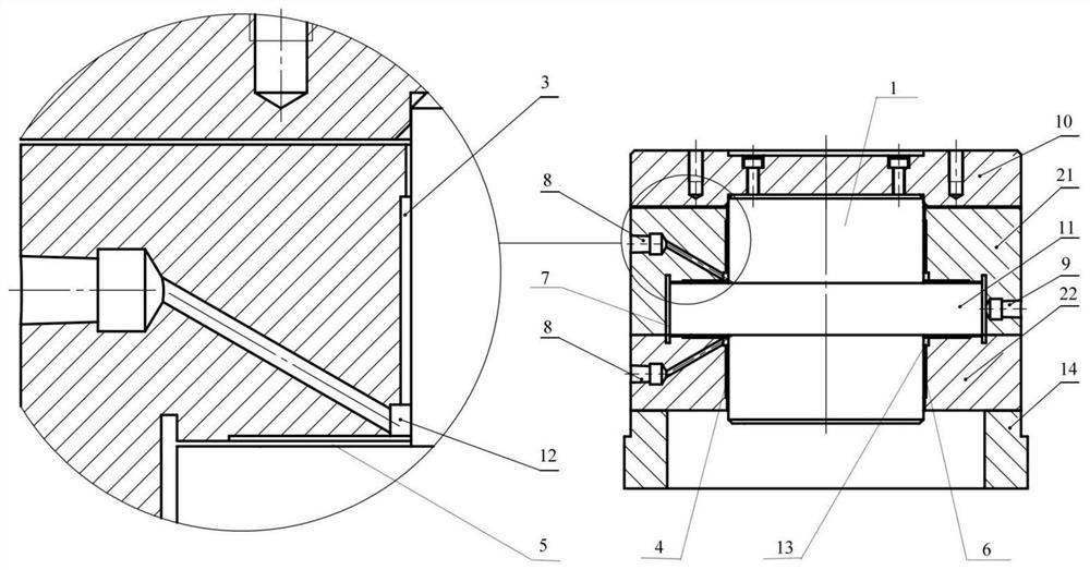
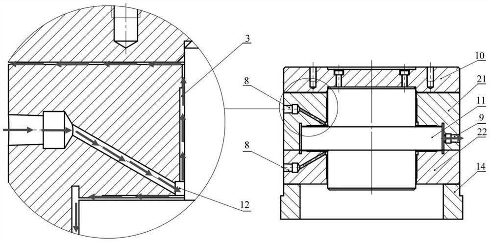
[0022] A hydrostatic bearing, comprising a main shaft 1 and a shaft sleeve 2, the main shaft 1 is a cylindrical structure with an annular flange 11 in the middle, the longitudinal section of the main shaft 1 is in the shape of a "middle", the The shaft sleeve 2 is a cylindrical structure with an annular groove in the middle, and the shaft sleeve 2 is set on the main shaft 1, and keeps the main shaft 1 and the shaft sleeve 2 with The coaxiality, the annular flange 11 is located inside the annular groove, a gap of 2-30 μm is maintained between the shaft sleeve 2 and the main shaft 1, the cylindrical structure above the annular flange 11 and the shaft sleeve There is an annular hole I3 between the two, and an annular hole II4 is arranged between the cylindrical structure below the annular flange 11 and the sleeve 2. The annular hole I3 and the annular hole II4 have the same structure and are symmetrical to each other. , the longitudinal sections of the annular aperture I3 and th...

specific Embodiment approach 2

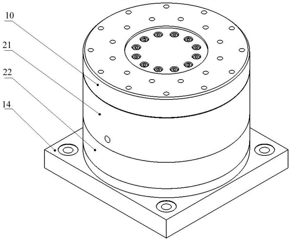
[0037] A hydrostatic turntable, including the hydrostatic bearing described in Embodiment 1 and the turntable base 14, the turntable base 14 is located under the shaft sleeve 2 and is fixedly connected and positioned with the shaft sleeve 2, as image 3 shown.

specific Embodiment approach 3

[0038] A surface throttling hydrostatic spindle: including the hydrostatic bearing described in Embodiment 1 and the spindle base 15, the spindle base 15 is located below the bushing 2 and is fixedly connected to the bushing 2, as Figure 4 shown.


PUM

PropertyMeasurementUnit
widthaaaaaaaaaa

Abstract

In order to provide a hydrostatic bearing with simple structure, convenient processing, good stability and high rotation precision, the present invention describes a hydrostatic bearing, which includes a main shaft and a shaft sleeve. The main shaft is a cylinder with an annular flange in the middle. The shaft sleeve is a cylindrical structure with an annular groove in the middle, the shaft sleeve is set on the main shaft, the annular flange is located inside the annular groove, the cylindrical structure above the annular flange and the shaft sleeve There is an annular hole Ⅰ between them, an annular hole Ⅱ is arranged between the cylindrical structure under the annular flange and the shaft sleeve, and an annular hole Ⅲ is arranged between the upper surface of the annular flange and the shaft sleeve. An annular aperture IV is provided between the lower surface of the annular flange and the shaft sleeve, and the longitudinal sections of the annular aperture I, the annular aperture II, the annular aperture III and the annular aperture IV all have a stepped structure. The invention has the advantages of less parts, simple processing, convenient assembly, no additional installation of throttle, more stable operation and higher reliability.

Description

technical field [0001] The invention belongs to the field of hydrostatic sliding bearings, and in particular relates to a fluid static pressure bearing, a fluid static pressure turntable and a fluid static pressure main shaft. Background technique [0002] Hydrostatic sliding bearings usually use fluid (liquid, gas, etc.) as the lubricant, and rely on the pressure source provided by the outside to form a lubricating film around the main shaft. The lubricating film can completely float the main shaft and provide support stiffness for the main shaft. The most notable advantage of sliding bearings is high precision. The lubricating film has an error homogenizing effect, which reduces the influence of workpiece machining errors on the rotation accuracy. Compared with dynamic pressure sliding bearings, the lubricating film of hydrostatic sliding bearings is more stable. The lubricating film can keep intact when running at high speed, and theoretically it can work without wear. W...

Claims


Application Information

Patent Timeline
Patent Type & Authority Patents(China)
IPC IPC(8): F16C32/06B23B19/02
CPCF16C32/0614F16C32/064F16C32/0655F16C32/0662F16C32/0696B23Q1/70F16C2322/39
Inventor 王波吴言功乔政丁飞韩睿
Owner HARBIN INST OF TECH
Why Eureka
Try Eureka