
Underground engineering foundation slab structure and construction method thereof

A technology for foundation floor and underground engineering, applied in underwater structures, hydraulic engineering, infrastructure engineering and other directions, can solve problems such as poor pressure bearing effect, floor cracking, easy damage, etc., to achieve not easy edge collapse, good pressure bearing effect , the effect of firmness enhancement

Active Publication Date: 2020-08-25
广东佰业泰建设工程有限公司
View PDF7 Cites 2 Cited by
  • Summary
  • Abstract
  • Description
  • Claims
  • Application Information

AI Technical Summary

Problems solved by technology

[0005] In view of the above situation, in order to overcome the defects of the prior art, the present invention provides an underground engineering foundation floor structure and its construction method, which effectively solves the problem of the poor pressure bearing effect of the underground structure engineering foundation floor and its construction and use method on the market. The floor is prone to local cracking, which affects the service life and stability of the floor. The lack of protective measures around the floor is prone to edge collapse, which affects the normal use of the entire floor. The level of the bottom of the floor is different, and the pressure capacity of the floor Uneven, easily damaged problems

Method used


Image

  • Underground engineering foundation slab structure and construction method thereof
  • Underground engineering foundation slab structure and construction method thereof
  • Underground engineering foundation slab structure and construction method thereof

Examples


Embodiment Construction

[0059] The technical solutions in the embodiments of the present invention will be clearly and completely described below in conjunction with the accompanying drawings in the embodiments of the present invention. Obviously, the described embodiments are only some of the embodiments of the present invention, not all of them; based on The embodiments of the present invention and all other embodiments obtained by persons of ordinary skill in the art without making creative efforts belong to the protection scope of the present invention.

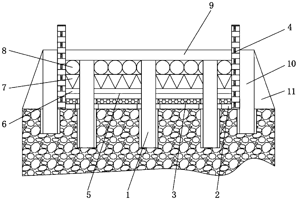
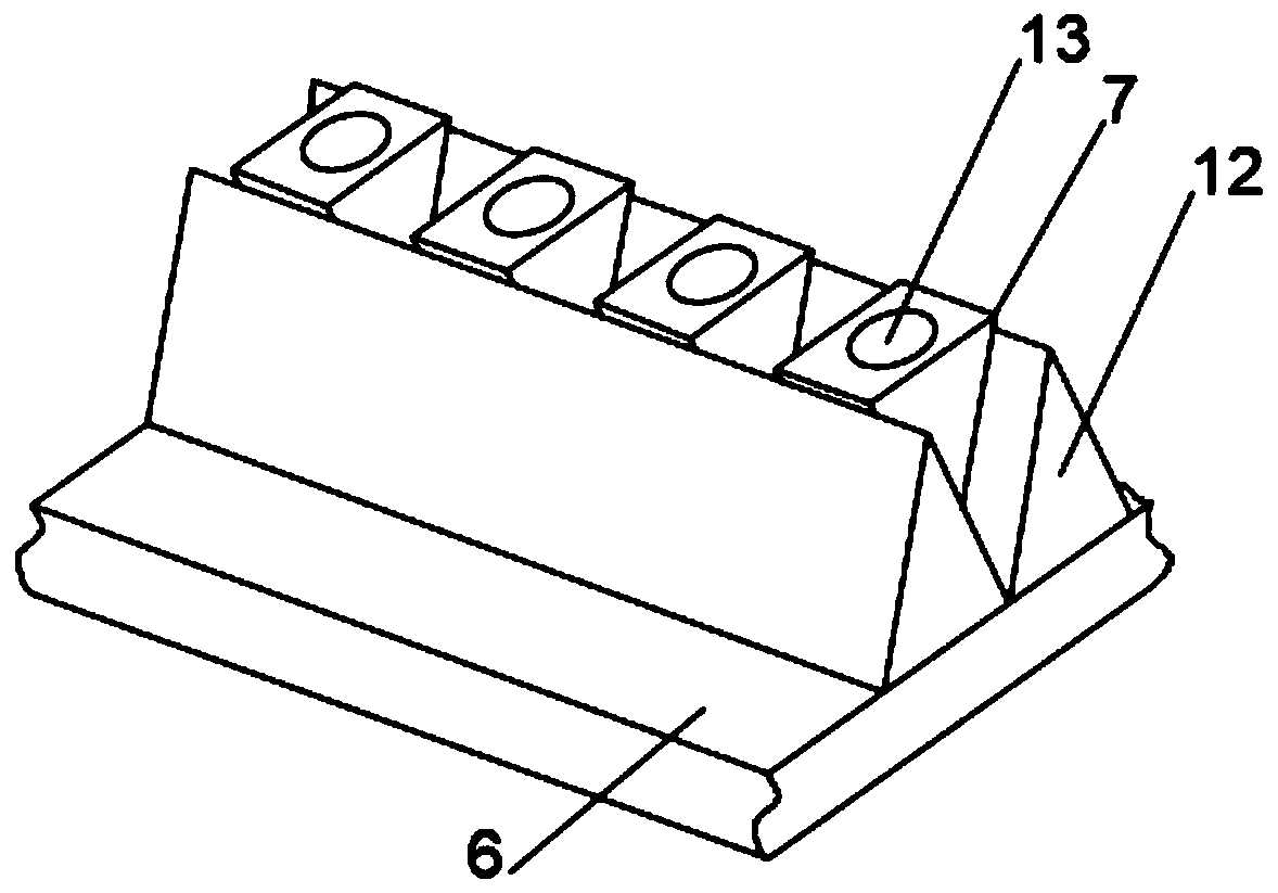
[0060] as attached figure 1 , 2 and 3,

[0061] The first technical aspect of the present invention is to provide a base plate structure for underground engineering, including a hard ground base, a base plate 9 and artificial hole-digging piles 1; 4. Build a pair of left and right symmetrical masonry on the surface of the hard base, and the bottom plate 9 is horizontally fixed between the left and right permanent protection walls 4; , reserve...


PUM


Abstract

The invention relates to the technical field of underground structural engineering and discloses an underground engineering foundation slab structure and a construction method thereof. The undergroundengineering foundation slab structure and the construction method thereof solve the problems that an underground structural engineering foundation slab and a construction and use method thereof in the current market have poor pressure-bearing effect, the slab is easy to generate the condition of local cracking, the service life and the stability of the slab are influenced, the peripheral protection measures of the slab are lacked, the condition of edge collapse is easy to occur, the normal use of the whole slab is influenced, the horizontal heights of laying things at the bottom of the slab are different, the pressure-bearing capacity of the slab is uneven, and the slab is prone to damage. The underground engineering foundation slab structure comprises manual hole digging piles, a lime layer is paved at one end of each manual hole digging pile, and a waterproof layer is paved on the lime layer. The underground engineering foundation slab structure and the construction method thereof have the advantages of good pressure-bearing effect, no local cracking due to large pressure, long service life and good stability, the periphery of the slab is well protected, edge collapse is not prone to occurring, the slab is stably used, the horizontal heights of the laying things are the same, the pressure borne by the slab is uniform, and the slab is not prone to damage.

Description

technical field [0001] The invention belongs to the technical field of underground building construction, in particular to an underground engineering foundation floor structure and a construction method thereof. Background technique [0002] Underground structures are divided into arched structures, circular and rectangular tubular structures, frame structures, thin shell structures, and special-shaped structures according to their structural forms. The loads borne by underground structures are divided into the following three categories according to their functional characteristics and possible situations during use. : That is, permanent (main) loads, variable (additional) loads and occasional (special) loads. [0003] However, the base floor structure used in the underground engineering currently on the market is laid layer by layer by filling the upper and lower layers in sequence, which will lead to: when the foundation floor structure is used, the upper part of the foun...

Claims


Application Information

Patent Timeline
Patent Type & Authority Applications(China)
IPC IPC(8): E02D29/045E02D31/02E02D27/12E02D27/14
CPCE02D27/12E02D27/14E02D29/045E02D31/02E02D31/025
Inventor 许庆仁许翔宇洪钦浩许清强陈小丽吴美金
Owner 广东佰业泰建设工程有限公司
Learn More