
Motor rotor punching sheet forming machining process

A technology for forming and processing motor rotors, used in metal processing equipment, manufacturing stator/rotor bodies, manufacturing tools, etc., can solve problems such as increased mass of supporting devices, blockage of worktables, inconvenient feeding, etc., and achieve continuous and stable work. , the effect of preventing accumulation

Active Publication Date: 2020-08-25
常州宝捷冲片有限公司
View PDF9 Cites 2 Cited by
  • Summary
  • Abstract
  • Description
  • Claims
  • Application Information

AI Technical Summary

Problems solved by technology

[0003] However, the motor rotor punching forming process in the current market has the following problems in the operation process: a. When the traditional motor rotor punching forming process is punching and forming the silicon steel sheet, the formed silicon steel sheet is easy to be nested in the stamping On the head, when the silicon steel sheet is manually squeezed and separated, the formed silicon steel sheet is easy to fall to the workbench, which is not convenient for feeding and will cause blockage of the workbench; b. Due to the traditional motor rotor punching forming process During the punching operation of the process, the formed silicon steel sheets will be separated into the supporting device, and as the number of punched sheets increases, large-scale accumulation of silicon steel sheets will appear on the supporting device, which will increase the quality of the entire supporting device. If the size of the supporting device is too large, the supporting device cannot work normally or the working cycle is short, and manpower is required to remove the accumulated silicon steel sheets in a timely manner

Method used


Image

  • Motor rotor punching sheet forming machining process
  • Motor rotor punching sheet forming machining process
  • Motor rotor punching sheet forming machining process

Examples


Embodiment Construction

[0037] In order to make the technical problems, technical solutions and beneficial effects to be solved by the present invention clearer, the present invention will be further described in detail below in conjunction with the accompanying drawings and embodiments. It should be understood that the specific embodiments described here are only used to explain the present invention, not to limit the present invention.

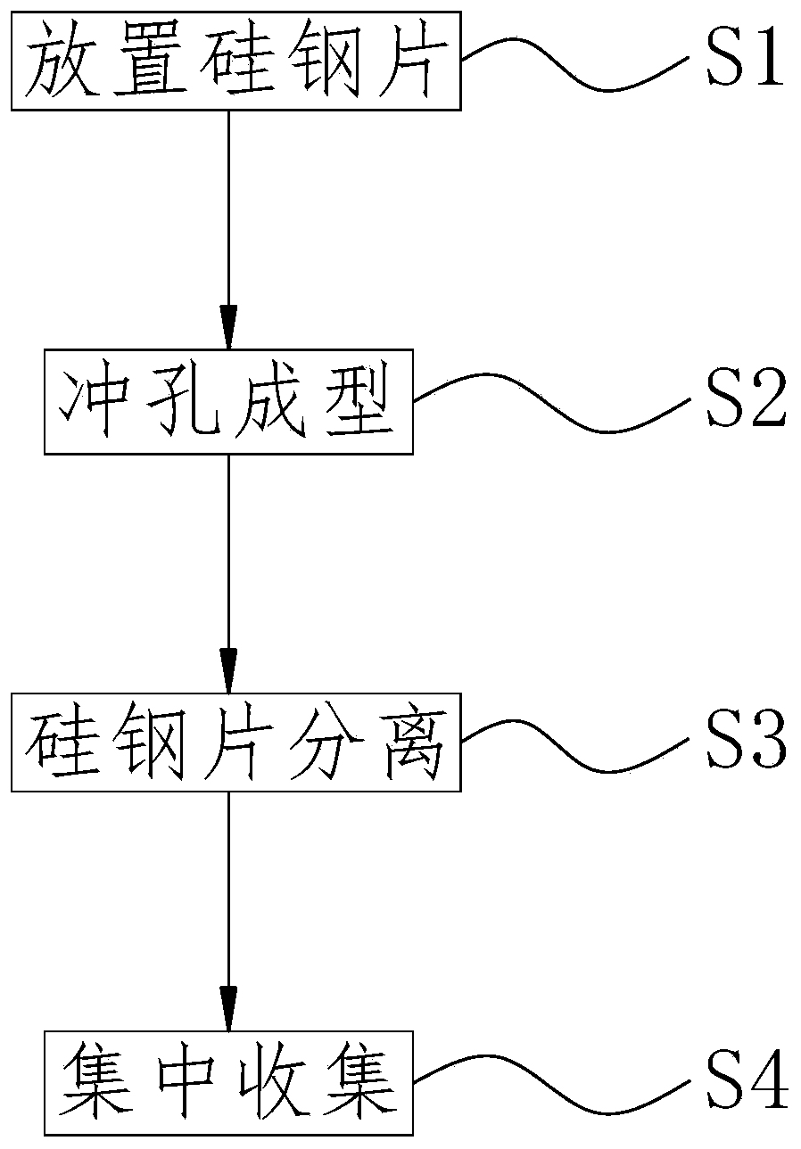
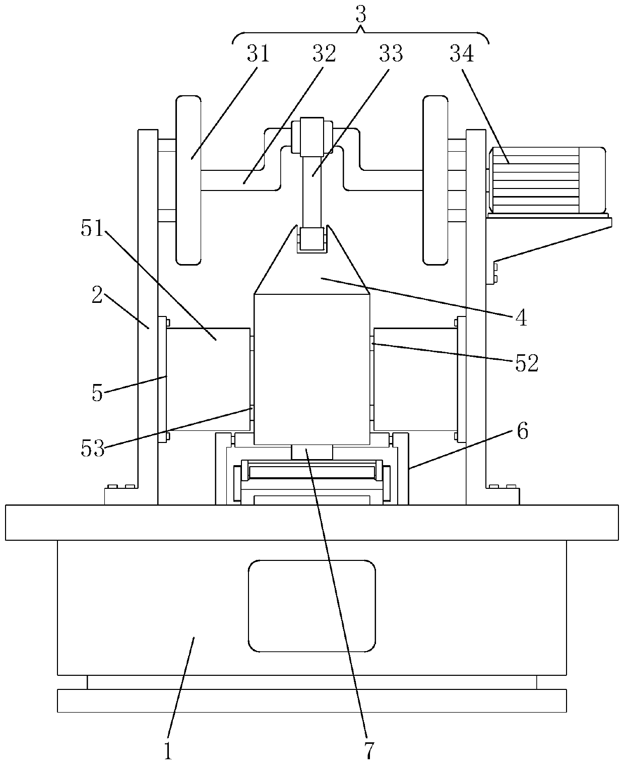
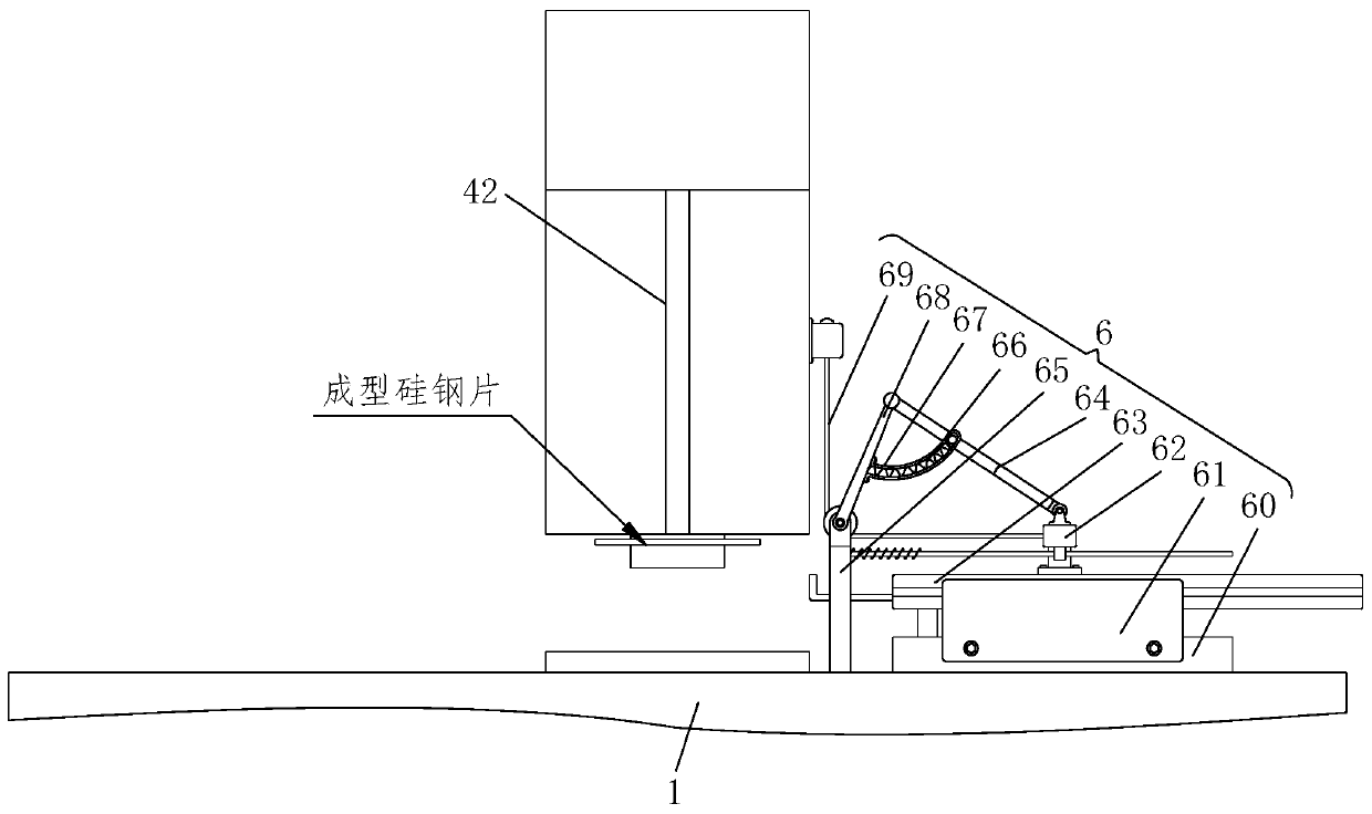
[0038]Refer to 1-11, a motor rotor punching forming process, which uses a motor rotor punching forming device, the waterproof membrane laying construction device includes a workbench 1, a support plate 2, a driving mechanism 3, The terminal connection block 4, the limit separation mechanism 5, the material receiving mechanism 6 and the stamping terminal 7, the specific method of punching the silicon steel sheet with the above-mentioned motor rotor punching forming processing device is as follows:

[0039] S1. Place the silicon steel sheet: place the silicon steel s...


PUM


Abstract

The invention relates to a motor rotor punching sheet forming machining process. The motor rotor punching sheet forming machining process comprises a workbench, supporting plates, a driving mechanism,an end connecting block, limiting separation mechanisms, a material receiving mechanism and a punching end, wherein the supporting plates are symmetrically arranged at the top of the workbench, the driving mechanism is arranged at the tops of the supporting plates, the lower end of the driving mechanism is connected with the end connecting block, the punching end is arranged at the center of thebottom of the end connecting block, the two side walls of the end connecting block are connected with the limiting separation mechanisms, one side of each limiting separation mechanism is connected with the side wall of one supporting plate, the material receiving mechanism is arranged behind the end connecting block, and the mounting plane of the material receiving mechanism is located between the lower end face of the punching end and the upper end face of the workbench. According to the motor rotor punching sheet forming machining process, the falling formed silicon steel sheets are rapidlycollected through the material receiving mechanism, so that the formed silicon steel sheets cannot fall onto the surface of the workbench, and meanwhile, the material receiving mechanism can rapidlythrow out the collected formed silicon steel sheets, so that the continuity of the whole discharging process is guaranteed.

Description

technical field [0001] The invention relates to the technical field of motor processing, in particular to a punching and forming process of a motor rotor. Background technique [0002] The motor rotor is also a rotating part in the motor. The motor is composed of two parts: the rotor and the stator. It is a conversion device used to realize electrical energy and mechanical energy and mechanical energy and electrical energy. The motor rotor is divided into a motor rotor and a generator rotor. The motor rotor is divided into two types: inner rotor rotation mode and outer rotor rotation mode. The rotation mode of the inner rotor is that the core body in the middle of the motor is a rotating body, which outputs torque (referring to the motor) or receives energy (referring to the generator). The rotation mode of the outer rotor is to use the outer body of the motor as the rotating body, and different modes facilitate the application in various occasions. No matter what kind of...

Claims


Application Information

Patent Timeline
IPC IPC(8): B21D28/26B21D28/04B21D45/00B21D43/20H02K15/02
CPCB21D28/04B21D28/265B21D43/20B21D45/003H02K15/02
Inventor 郭公升许旭闫宇
Owner 常州宝捷冲片有限公司
Learn More