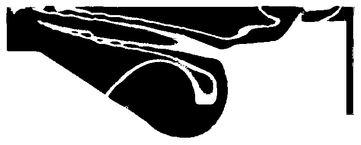
Combustion chamber of diesel engine
A combustion chamber and diesel engine technology, applied to combustion engines, mechanical equipment, engine components, etc., can solve problems such as difficult to obtain nitrogen oxides, achieve the effects of inhibiting the generation of harmful substances, not reducing thermal efficiency, and reducing heat loss
- Summary
- Abstract
- Description
- Claims
- Application Information
AI Technical Summary
Problems solved by technology
Method used
Image
Examples
Embodiment 1
[0045] see figure 1 , figure 1 It is a structural schematic diagram of a combustion chamber of a diesel engine provided by an embodiment of the present invention. The combustion chamber is a symmetrical structure with its central line as the axis of symmetry, and can be formed by one rotation around the central line. The combustion chamber includes: a central platform 1, a pit area M, a lip 5, a step area N and a piston top 7; wherein,
[0046] The central platform 1 is located in the center of the combustion chamber; the pit area M is concave, and the boundary curve 3 of the pit area is located at the bottom of the combustion chamber, and is in the shape of a circular arc, which is a curvature circle with a fixed radius R1, and one end of it faces the side of the central platform. The platform side busbar 2 extending from the bottom of the combustion chamber is connected to each other, and the other end is connected to the lip 5 through the guide line 4 extending to the top...
PUM
 Abstract
Description
Claims
Application Information
 - R&D
- Intellectual Property
- Life Sciences
- Materials
- Tech Scout
- Unparalleled Data Quality
- Higher Quality Content
- 60% Fewer Hallucinations
Browse by: Latest US Patents, China's latest patents, Technical Efficacy Thesaurus, Application Domain, Technology Topic, Popular Technical Reports.
© 2025 PatSnap. All rights reserved.Legal|Privacy policy|Modern Slavery Act Transparency Statement|Sitemap|About US| Contact US: help@patsnap.com


