An optical fiber loosening device

A loose, optical fiber technology, applied in the direction of fiber mechanical structure, etc., can solve the problems of poor consistency, fiber corrosion, large diameter difference, etc., and achieve the effect of good diameter consistency, reliability and stability.

Active Publication Date: 2022-08-02
JIANGSU HENGTONG OPTICAL FIBER TECH +1
View PDF4 Cites 0 Cited by
  • Summary
  • Abstract
  • Description
  • Claims
  • Application Information

AI Technical Summary

Problems solved by technology

In the prior art, manual winding is usually used to obtain unstressed fiber rings or fiber rings, and the diameter of fiber rings or fiber rings cannot be well controlled, so that the test requirements cannot be met.
Moreover, the diameters of the optical fiber rings or optical fiber rings of each circle have large differences and poor consistency, which leads to the fact that optical fibers with large effective areas or single-mode optical fibers that are not sensitive to bending loss cannot filter well when testing parameters such as cut-off wavelength. In addition to high-order wavelengths, the stability and consistency of test results are poor
[0003] Moreover, in the process of manually winding the optical fiber, the human hand is always in contact with the optical fiber, and dust and sweat will adhere to the optical fiber, which will easily cause corrosion to the optical fiber and affect the test results when the optical fiber ring or optical fiber ring is used as a sample for environmental testing.

Method used


Image

  • An optical fiber loosening device
  • An optical fiber loosening device
  • An optical fiber loosening device

Examples


Embodiment Construction

[0033] In order to make the technical problems solved by the present invention, the technical solutions adopted and the technical effects achieved more clearly, the technical solutions of the present invention are further described below with reference to the accompanying drawings and through specific embodiments. It should be understood that the specific embodiments described herein are only used to explain the present invention, but not to limit the present invention. In addition, it should be noted that, for the convenience of description, the accompanying drawings only show some but not all of the parts related to the present invention.

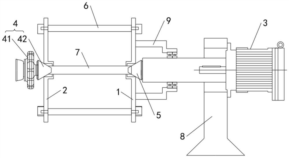
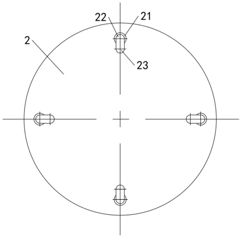
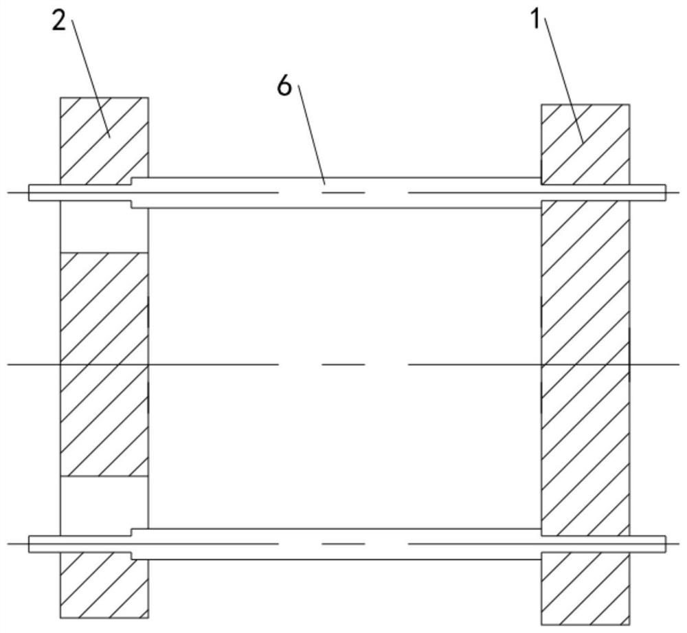
[0034] like Figure 1 to Figure 4 As shown, this embodiment provides an optical fiber loosening device, which includes a first fixed disk 1, a second fixed disk 2, a plurality of support rods 6 and a driving unit 3, wherein the first fixed disk 1 and the second fixed disk 2 are parallel. and arranged at intervals; a plurality of support ...


PUM


Abstract

The invention relates to the technical field of optical fibers, and discloses an optical fiber loosening device, comprising a first fixed disk and a second fixed disk arranged in parallel and spaced apart, and a plurality of support rods are arranged between the first fixed disk and the second fixed disk and circumferentially The two ends of the support rod are respectively connected to the first fixed plate and the second fixed plate; the output shaft of the drive unit is connected to the rotating shaft, and one end of the rotating shaft passes through the first fixed plate and the second fixed plate in sequence and can be detachably connected to the clamping assembly. The second fixing disc of the optical fiber loosening device provided by the present invention can be rotated relative to the first fixing disc, so that the outer diameter of the middle position of the winding core is reduced, and the outer diameter of the end near the second fixing disc is also reduced, so that the support rod is The fiber becomes loose, the stability of loosening the fiber is good, and the diameter of the obtained loose fiber is consistent, which ensures the reliability of the test results; instead of manually winding the fiber, the fiber coil can be removed without damage, and the maximum Minimized impact on subsequent tests.

Description

technical field [0001] The invention relates to the technical field of optical fibers, in particular to an optical fiber loosening device. Background technique [0002] Before testing the fiber, it is necessary to obtain an unstressed fiber ring or fiber optic coil. In the prior art, the unstressed optical fiber ring or the optical fiber coil is usually obtained by manual winding, and the diameter of the optical fiber ring or the optical fiber coil cannot be well controlled, so that the test requirements cannot be met. In addition, the diameters of the fiber rings or fiber rings of each circle are quite different and the consistency is poor, which leads to the fact that the fiber with a large effective area or the single-mode fiber that is not sensitive to bending loss cannot be well filtered when testing parameters such as cut-off wavelength. Except for high-order wavelengths, the stability and consistency of the test results are poor. [0003] Moreover, in the process of...

Claims


Application Information

Patent Timeline
Patent Type & Authority Patents(China)
IPC IPC(8): G02B6/44
CPCG02B6/44
Inventor 李永通孙伟陈伟朱永刚严勇虎张功会郝军杰王林袁建超罗干管弘丰周忠凯郝昌平徐陆锋许明通
Owner JIANGSU HENGTONG OPTICAL FIBER TECH
Why Eureka
Try Eureka