
MEMS vibratory gyroscope structure and manufacturing method thereof

A gyroscope, vibrating technology, applied in the field of MEMS vibrating gyroscope structure and its manufacturing, can solve the problems affecting the geometric shape and material properties of the MEMS gyroscope, the accuracy and stability of the MEMS gyroscope, and the imbalance of the gyroscope microstructure. and other problems, to achieve the effect of improving the yield of the device, the method is simple and efficient, and the accuracy and performance are improved

Inactive Publication Date: 2020-08-18
江苏睦荷科技有限公司
View PDF16 Cites 3 Cited by
  • Summary
  • Abstract
  • Description
  • Claims
  • Application Information

AI Technical Summary

Problems solved by technology

Processing defects and processing errors will affect the geometry and material properties of the MEMS gyroscope, and change the resonant frequency of the gyroscope; at the same time, manufacturing defects and tolerances cause the imbalance of the gyroscope microstructure, resulting in mechanical interference between modes and positive Cross-coupling error, which is often much larger than Coriolis motion; in addition, there are non-ideal factors such as structural stress and mechanical noise during the operation of the device, which seriously affects the accuracy and stability of the MEMS gyroscope

Method used


Image

  • MEMS vibratory gyroscope structure and manufacturing method thereof
  • MEMS vibratory gyroscope structure and manufacturing method thereof
  • MEMS vibratory gyroscope structure and manufacturing method thereof

Examples


Embodiment 1

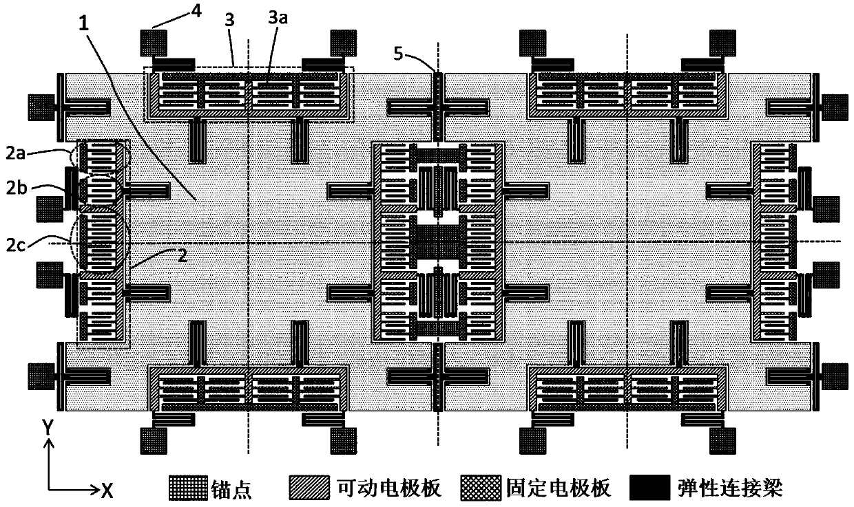
[0042] Embodiment 1: a kind of MEMS vibration type gyroscope, as figure 1 As shown, it includes a cover silicon wafer 10, a structural silicon wafer 9 and a substrate silicon wafer 6. The cover silicon wafer 10, the structural silicon wafer 9 and the substrate silicon wafer 6 are arranged layer by layer from top to bottom to form a vacuum chamber The "sandwich" structure of the MEMS vibrating gyroscope is installed on the structural silicon wafer 9 .

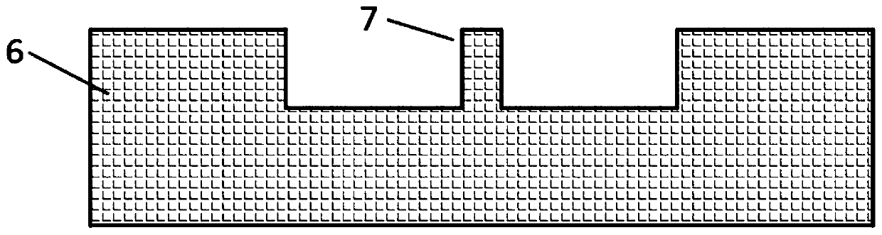
[0043] A cavity structure with support pillars 7 is provided on the substrate silicon wafer 6 , and a layer of silicon oxide layer 8 is deposited on both the front and back sides of the substrate silicon wafer 6 .

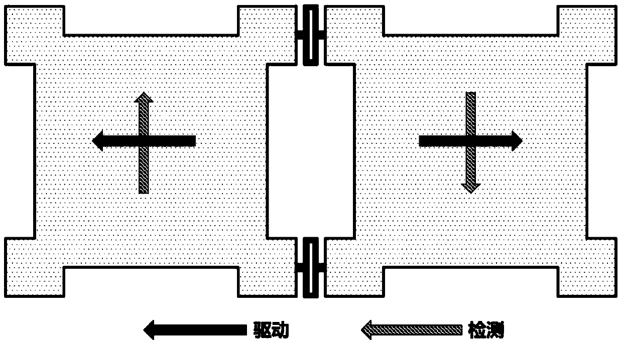
[0044] Such as figure 1 As shown, the devices installed on the structural silicon wafer 9 include two mass blocks 1 , four driving frames 2 , four detection frames 3 , several elastic connecting beams 5 and anchor points 4 . The two mass blocks 1 are arranged symmetrically at the left and right centers of the structu...

Embodiment 2

[0059] Embodiment 2: a kind of MEMS vibration type gyroscope, as Figure 4 As shown, the position of the quadrature compensation electrode 2a can be changed, and the quadrature compensation electrode 2a distributed at both ends of the driving frame 2 can be moved to the center position of the left and right masses 1, which can also realize the function of suppressing the quadrature coupling error. The scheme optimizes the electrode arrangement space and arrangement method, wherein various functional electrodes 21 can be flexibly arranged.


PUM


Abstract

The invention discloses an MEMS vibratory gyroscope and a manufacturing method thereof, and belongs to the field of MEMS gyroscope sensor design and processing. According to the technical scheme, thestructure is characterized by comprising a cover plate silicon wafer, a structure silicon wafer and a substrate silicon wafer, wherein the cover plate silicon wafer, the structure silicon wafer and the substrate silicon wafer are arranged layer by layer from top to bottom to form a structure with a vacuum cavity. A device is mounted on the structural silicon wafer. The device comprises two mass blocks, four driving frames, four detection frames, a plurality of elastic connecting beams and anchor points. The structure has the advantages that the vacuum packaging of the device is realized by adopting a vacuum bonding method, the method is simple and efficient, the yield of the device is improved, the preparation cost of the device is reduced, the method is suitable for batch production, andthe produced gyroscope can effectively inhibit errors and improve the precision and performance of the device.

Description

technical field [0001] The invention relates to the field of MEMS gyroscope sensor design and processing, in particular to a MEMS vibrating gyroscope structure and a manufacturing method thereof. Background technique [0002] Gyroscope is a sensor that measures the rotation angle or angular displacement of an object. It is used to realize the measurement and control of the attitude and trajectory of the moving carrier. It is one of the basic core components of the inertial navigation and guidance system. Compared with traditional mechanical and optical gyroscopes, micro-electro-mechanical system (MEMS) gyroscopes have the advantages of low cost, small size, low power consumption, and can be integrated with circuits. They are widely used in consumer electronics and medical electronics. , automotive electronics, aerospace and military and other fields, has great development potential and commercial value. The principle of the MEMS gyroscope is the Coriolis effect. The suspend...

Claims


Application Information

Patent Timeline
Patent Type & Authority Applications(China)
IPC IPC(8): G01C19/5621G01C19/5628
CPCG01C19/5621G01C19/5628
Inventor 李磬
Owner 江苏睦荷科技有限公司
Learn More