


Quick Research
Generate reliable direction feasibility study reports for your R&D in just a few steps.

Technical Q&A
Discover and master advanced knowledge NOW. Basics, ideas, possibilities, all at once.

Find Solutions
As an expert in R&D theories, this can generate solutions to your technical problems instantly.

Evaluate Feasibility
Analyze your overall solution with one click, know your potential R&D risks in advance.

Monitor Landscape
Get weekly tech updates, stay abreast of the latest tech innovations and key insights.
Aircraft radar stealth airfoil and production method thereof
A radar stealth and aircraft technology, applied in aircraft, unmanned aircraft, wings, etc., can solve the problems of limited structural space and low bonding force
- Summary
- Abstract
- Description
- Claims
- Application Information
AI Technical Summary
Problems solved by technology
Method used
Image

Examples
Embodiment 1
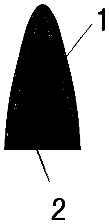
[0040] The shape of the leading edge section of the missile wing is as follows: figure 1 As shown, among them, the radius of the leading edge is 10mm, the wedge width is 25mm, the subsonic naca airfoil is adopted, and the relative thickness of the airfoil is 10%.
[0041] The airfoil is machined as follows:
[0042] (1) Processing metal materials
[0043] Adopt conventional construction technology to complete the processing and molding of the wing surface metal material;
[0044] (2) Processing of absorbing materials
[0045] After grinding and cleaning the surface of the metal material, apply commercially available radar wave-absorbing paint on the front edge of the metal material by spraying or brushing, and make the coating thickness reach or Exceeding the structural design thickness;
[0046] (3) post-processing
[0047] After the coating is cured, the part of the absorbing material that is higher than the designed thickness is polished and modified to ensure a smooth...
Embodiment 2
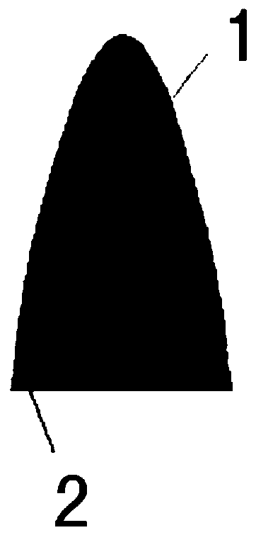
[0049] The shape of the leading edge section of the missile wing is as follows: figure 2 As shown, the radius of the leading edge is 5mm, the rear end of the wedge surface and the shape of the airfoil transition smoothly, the width of the wave-absorbing material is 30mm, and the subsonic naca airfoil is adopted, and the relative thickness of the airfoil is 10%.
[0050] The airfoil is machined as follows:
[0051] (1) Processing metal materials
[0052] Adopt conventional construction technology to complete the processing and molding of the wing surface metal material;
[0053] (2) Process absorbing material patch
[0054] According to the designed shape, the upper and lower patches consistent with the three-dimensional shape of the application part are prepared in the mold.
[0055] For the convenience of subsequent pasting, the upper and lower patches are prepared as adjacent whole pieces
[0056] (3) Pasting and molding of absorbing materials
[0057]After grinding an...
Embodiment 3
[0059] The shape of the leading edge section of the missile wing is as follows: figure 2 As shown, among them, the leading edge radius is 20mm, the rear end of the wedge surface and the wing shape transition smoothly, the wave-absorbing material paste width is 40mm, the subsonic naca airfoil is adopted, and the relative thickness of the airfoil is 12%.
[0060] The airfoil is machined as follows:
[0061] (1) Processing metal materials
[0062] Adopt conventional construction technology to complete the processing and molding of the wing surface metal material;
[0063] (2) Process absorbing material patch
[0064] According to the designed shape, the upper and lower patches consistent with the three-dimensional shape of the application part are prepared in the mold.
[0065] For the convenience of subsequent pasting, the upper and lower patches are prepared as adjacent whole pieces
[0066] (3) Pasting and molding of absorbing materials
[0067] After grinding and cleani...
PUM
| Property | Measurement | Unit |
|---|---|---|
| Radius | aaaaa | aaaaa |
Abstract
Description
Claims
Application Information
 - R&D Engineer
- R&D Manager
- IP Professional
- Industry Leading Data Capabilities
- Powerful AI technology
- Patent DNA Extraction
Browse by: Latest US Patents, China's latest patents, Technical Efficacy Thesaurus, Application Domain, Technology Topic, Popular Technical Reports.
© 2024 PatSnap. All rights reserved.Legal|Privacy policy|Modern Slavery Act Transparency Statement|Sitemap|About US| Contact US: help@patsnap.com