Straw picking and bundling machine

A baler and straw technology, which is applied in the field of straw picking and baling machines, can solve the problems of affecting the overall quality of feed, unfavorable continuous operation of equipment, and low density of straw baling

Pending Publication Date: 2020-08-14
吉林省凯迪农业机械制造有限公司
View PDF0 Cites 0 Cited by
  • Summary
  • Abstract
  • Description
  • Claims
  • Application Information

AI Technical Summary

Problems solved by technology

After crushing, these sundries are mixed in the straw feed, which affects the overall quality of the feed; during the pulverization process, the sundries will cause damage to the hammer claws and auger knives due to their own hardness, which is not conducive to the continuous operation of the equipment; The crushing effect of the hammer claw knife is low, and only the blades of the auger are crushed, and the number of crushing times is small. The actual crushing effect of straw crops is sometimes not ideal, resulting in a low density of straw bales when compressed and baled. The problem of poor drop resistance of the bales

Method used


Image

  • Straw picking and bundling machine
  • Straw picking and bundling machine
  • Straw picking and bundling machine

Examples


Embodiment Construction

[0034] In order to make the object, technical solution and advantages of the present invention clearer, the technical solution of the present invention will be described in detail below. Apparently, the described embodiments are only some of the embodiments of the present invention, but not all of them. Based on the embodiments of the present invention, all other implementations obtained by persons of ordinary skill in the art without making creative efforts fall within the protection scope of the present invention.

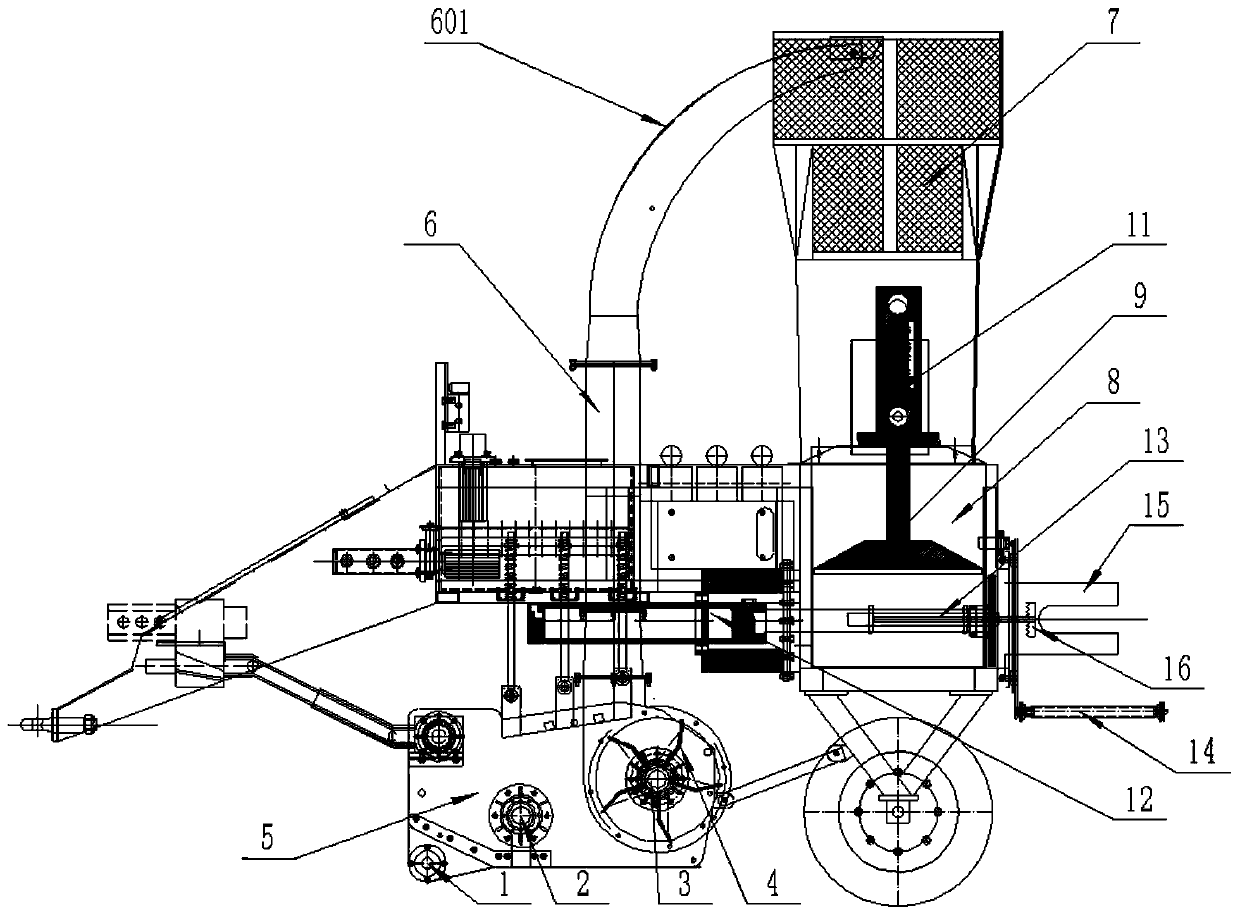
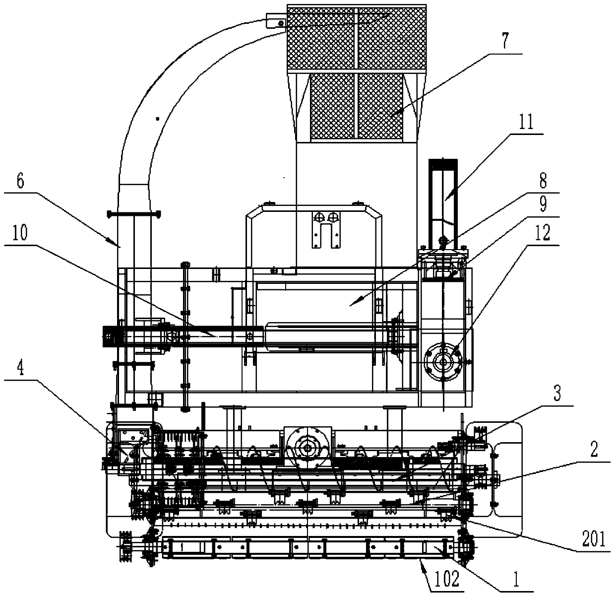
[0035] The purpose of this specific embodiment is to provide a straw picking and bundling machine, which is provided with a set of rotary knives at the mouth of the picking bin, and the hammer claw and auger are arranged downstream of the rotary knives. At the opening of the picking bin, the straw can be cut and picked up, and at the same time, it can effectively prevent bricks, stones, tiles, etc. from entering the picking bin, and has the functions of picking u...


PUM


Abstract

The invention discloses a straw picking and bundling machine. The straw picking and bundling machine comprises a traction frame, a pickup device, a feeding bin, a discharging bin, a compression chamber and a compression assembly located in the compression chamber, wherein the pickup device comprises a pickup bin, a rotary knife assembly, a hammer claw assembly, an auger assembly and a fan; the rotary knife assembly comprises a rotating shaft and a rotary knife which extend in the length direction of an opening of the pickup bin, and the rotary knife is in a long sheet shape; the fan communicates with the pickup bin; one end of the feeding bin is connected with the fan, the other end of the feeding bin faces the discharging bin, and the compression chamber communicates with the dischargingbin; the compression assembly comprises three pressing plates connected with the compression chamber in a sliding mode and three compression powers connected with the pressing plates in a one-to-one correspondence mode, the compression directions of the three pressing plates are perpendicular in pairs, a feeding port of the compression chamber is located in the compression stroke of the first horizontal compression direction, and a discharging port of the compression chamber is located on the downstream of the second horizontal compression direction. Straw can be cut and picked up, meanwhile,picking-up of bricks, stones, tiles and the like is reduced, and picking-up, cutting and smashing, sundry removing and bundling are integrated.

Description

technical field [0001] The invention relates to the technical field of straw recycling and processing, and more specifically relates to a straw picking and bundling machine. Background technique [0002] Straw can be used as feed for livestock after being recycled and crushed, which has great economic significance. The straw picking and bundling machine is this kind of straw recycling equipment, which picks up, collects, crushes, transports, compacts and bundles the straw in the field. The existing straw picking and bundling machines use the hammer claw knife located in the picking bin to pick up the straw, and then crush it through the blades of the auger and transport it to the silo by the fan, and then it is compacted and bundled before outputting to form a straw. Bundles of feed. But the hammer claw cutters in the prior art are all small single cutters with three teeth, and a plurality of hammer claw cutters are distributed on the rotating hammer claw shaft, and the wh...

Claims


Application Information

Patent Timeline
Patent Type & Authority Applications(China)
IPC IPC(8): A23N17/00A01F29/01A01F29/04A01F29/09A01F29/16A01D89/00B65B11/02B65B41/12B65B61/10B30B9/30G01G17/00
CPCA01D89/001A01F29/01A01F29/04A01F29/09A01F29/16A23N17/00B30B9/3003B65B11/02B65B41/12B65B61/10G01G17/00
Inventor 王贯
Owner 吉林省凯迪农业机械制造有限公司
Why Eureka
Try Eureka