
Pressure sensor system for compressor outlet pressure measurement

A pressure sensor and compressor technology, which is used in measurement devices, rapid changes in measurement, instruments, etc., can solve the problems of large delay in measurement systems, inability to compensate for algorithms, and low accuracy, and achieve the effect of meeting the needs of reliability.

Active Publication Date: 2020-07-31
NANJING UNIV OF AERONAUTICS & ASTRONAUTICS
View PDF6 Cites 2 Cited by
  • Summary
  • Abstract
  • Description
  • Claims
  • Application Information

AI Technical Summary

Problems solved by technology

[0004] (1) Changes in engine operating conditions, length of bleed air pipe, structural parameters and temperature affect the total pressure recovery coefficient, making the measured pressure unable to accurately and timely reflect the desired result;
[0005] (2) The pressure scanning valves are all imported, and there is no system-level optimization design with the probe and bleed air pipe, and it is impossible to compensate in the subsequent algorithm
[0007] (1) In surge monitoring and control, the solution based on total pressure and static pressure judgment mainly uses diaphragm bellows pressure sensor, which has the problems of low precision, large temperature drift, and poor sensor reliability, which is easy to cause false alarm or The problem of misjudgment,
[0008] (2) Due to the large delay of the measurement system and poor dynamic characteristics, the stall prediction cannot be implemented;
[0009] (3) Due to the lack of research on comprehensive optimization design of working conditions, bleed air pipelines, and measurement algorithms, the anti-breathing scheme that only uses static pressure has a high false alarm rate and cannot be applied on airborne

Method used


Image

  • Pressure sensor system for compressor outlet pressure measurement
  • Pressure sensor system for compressor outlet pressure measurement
  • Pressure sensor system for compressor outlet pressure measurement

Examples


Embodiment Construction

[0033] The technical solution of the present invention will be described in detail below in conjunction with the accompanying drawings.

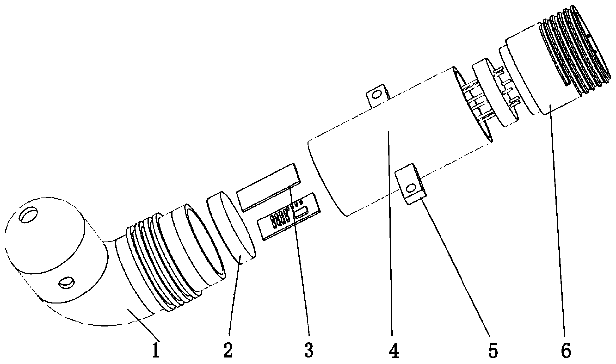
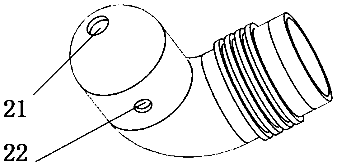
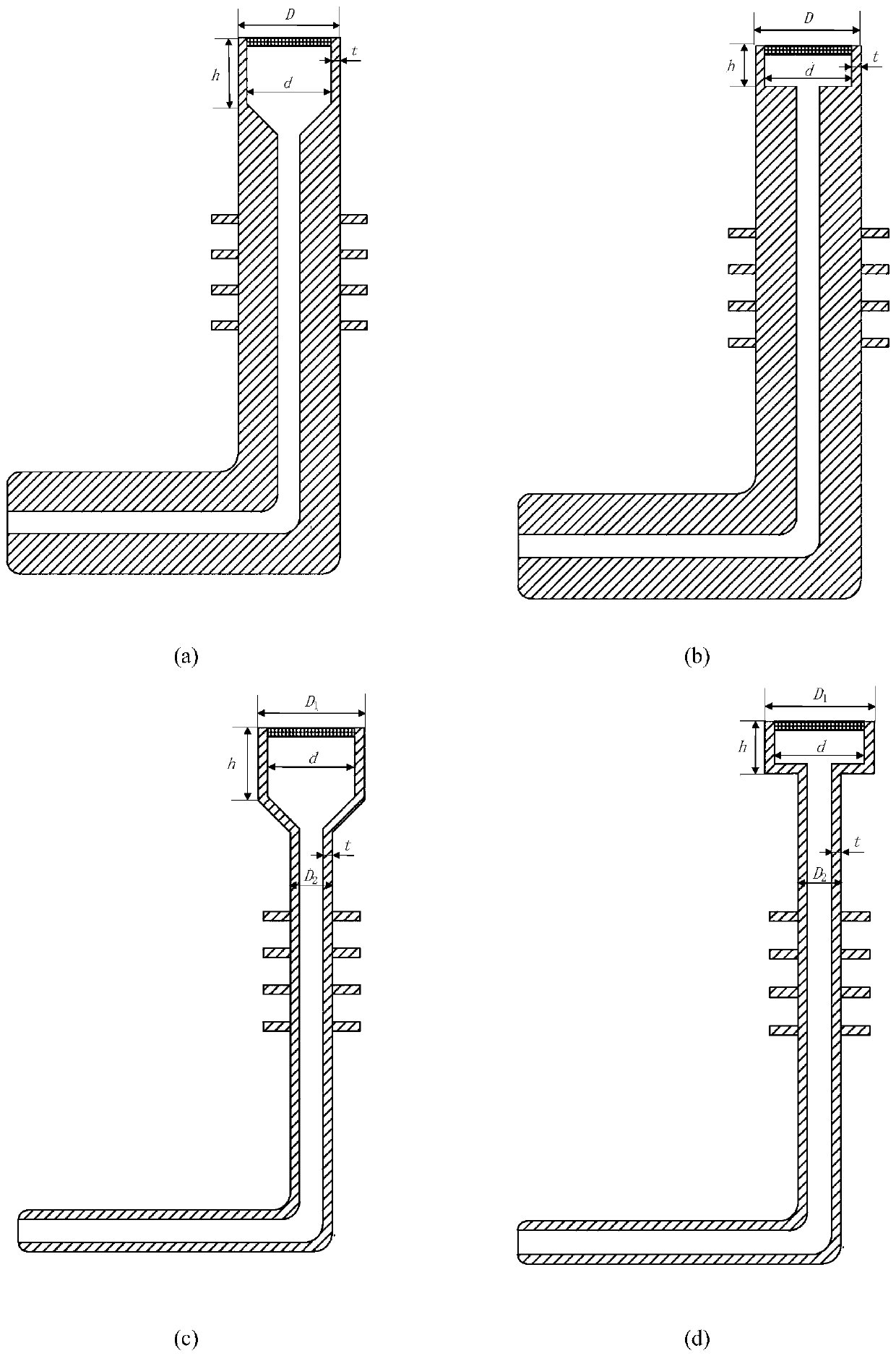
[0034] figure 1 It is the overall structure of the structural scheme of the pressure sensor (referred to as: dynamic pressure sensor) for measuring the outlet pressure of the compressor. figure 1 Among them are a short measuring tube 1, a pressure sensitive device 2, a signal processing module 3, a pressure housing 4, a fixing seat 5, and an output signal line connector 6. The dynamic pressure sensor of the present invention consists of short measuring tube 1 (including total pressure hole 21, static pressure hole 22 and annular ribs), pressure sensitive device 2, signal processing module 3, pressure housing 4, output signal Wire connector6. Wherein, the pressure sensitive device 2 and the signal processing module 3 are located in the pressure housing 4, and the housing is filled with protective insulating glue. The pressure sensitive dev...


PUM

PropertyMeasurementUnit
thermal conductivityaaaaaaaaaa
thicknessaaaaaaaaaa

Abstract

The invention discloses a pressure sensor system for compressor outlet dynamic pressure measurement. Compressor outlet pressure is collected and output as a voltage signal by a pressure sensitive device through a short measuring tube, and the voltage signal is processed by a signal processing module into a temperature compensated voltage signal to be output. A compressor outlet dynamic pressure sensor system is jointly formed based on the short measuring tube, the pressure sensitive device, the signal processing module, a pressure shell, a fixed seat and an output signal line connector. The system can reliably and accurately obtain the dynamic total pressure at high temperature, and has important significance for engine fault diagnosis.

Description

technical field [0001] The invention relates to a pressure sensor system for measuring the outlet pressure of a compressor, which belongs to the field of aeroengine control. Background technique [0002] The total pressure signal of the compressor outlet airflow has three characteristics - high temperature, fast dynamic response and fast stagnation of the airflow. Usually the temperature range of the engine inlet airflow is -50℃~+65℃. After being compressed by the compressor, the outlet air temperature will be as high as several hundred degrees Celsius. For example, the outlet air temperature of a high-pressure compressor of a turbofan engine can reach 600°C. Most current pressure sensitive components cannot work at this high temperature. The change and propagation speed of gas pressure is fast. Compared with the temperature, speed and other signals in the engine, the pressure is a fast-changing signal. When a rotating stall occurs, the total pressure of the compressor wi...

Claims


Application Information

Patent Timeline
Patent Type & Authority Applications(China)
IPC IPC(8): G01L23/08G01L23/18G01L23/26
CPCG01L23/08G01L23/18G01L23/26
Inventor 潘慕绚刘杨琳武乐群黄金泉
Owner NANJING UNIV OF AERONAUTICS & ASTRONAUTICS
Learn More