A CNC lathe with alarm function

A technology of CNC lathes and functions, applied in the field of CNC lathes, can solve the problems of rust, coolant accumulation, and clogging of waste chips of CNC machine tools.

Active Publication Date: 2021-06-15
三星智能科技盐城有限公司
View PDF0 Cites 0 Cited by
  • Summary
  • Abstract
  • Description
  • Claims
  • Application Information

AI Technical Summary

Problems solved by technology

[0004] For the existing CNC lathes with alarm function, a large amount of waste chips will be generated during the processing of parts by the CNC machine tools, and these waste chips will fall together with the coolant. When the coolant is recycled, the waste chips will block At the recovery port, the coolant is accumulated in the CNC machine tool, causing the CNC machine tool to rust. The present invention provides a CNC lathe with an alarm function to solve the above technical problems

Method used


Image

  • A CNC lathe with alarm function
  • A CNC lathe with alarm function
  • A CNC lathe with alarm function

Examples


Embodiment 1

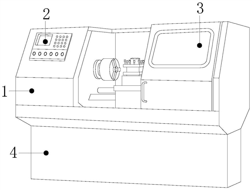
[0026] see Figure 1-Figure 4 :

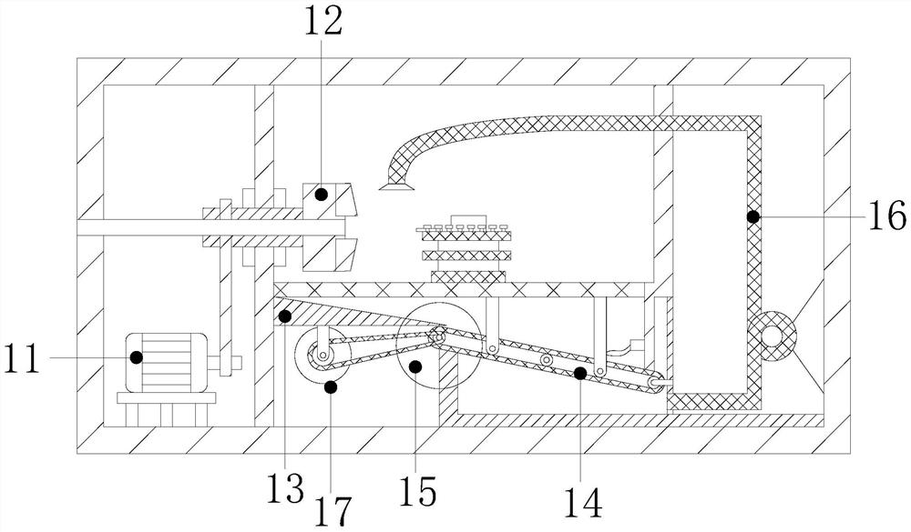
[0027] A CNC lathe with an alarm function, its structure includes a CNC body 1, a control panel 2, an observation port 3, and a base 4, the CNC body 1 is connected above the base 4 by welding, and the control panel 2 is installed on the CNC body 1 surface, the observation port 3 is embedded in the surface of the CNC body 1, which is characterized in that the CNC body 1 includes a motor 11, a clamp 12, a baffle 13, a material guide belt 14, a separation device 15, a water pipe 16, and a transmission 17. The motor 11 is connected to the inner bottom of the CNC machine body 1 by welding, the clamp 12 is fitted on the top of the motor 11, the baffle plate 13 is embedded in the inner wall of the CNC machine body 1, the material guide belt 14 and the separation device 15 Installed below the baffle plate 13, the water pipe 16 is located inside the CNC machine body 1, the transmission machine 17 is installed on the bottom of the baffle plate 13 and c...

Embodiment 2

[0032] see Figure 5-Figure 7 :

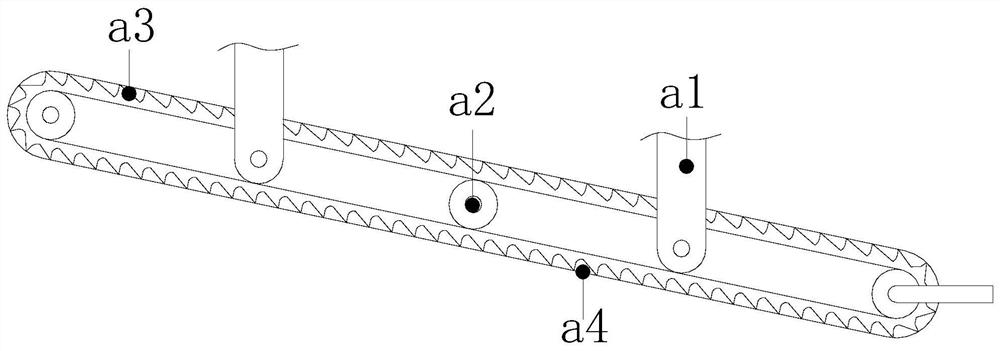
[0033] In the figure, the separation device 15 includes a conveyor belt b1, a bite groove b2, a drive shaft b3, and a support rod b4. The conveyor belt b1 connects the transmission 17 to the outside of the drive shaft b3, and the bite groove b2 is embedded in the inside of the conveyor belt b1. The support rod b4 is placed directly below the drive shaft b3, and the support rod b4 is connected to the inner bottom of the CNC machine body 1 by welding. The top of the support rod b4 is close to the surface of the isolation belt a3, which is beneficial to the removal of waste in the waste chip chute a4. debris to clean up.

[0034] In the figure, the drive shaft b3 includes a bearing b31, a rotating roller b32, and teeth b33. The rotating roller b32 is embedded and fixed around the bearing b31. The teeth b33 are connected to one side of the rotating roller b32 by welding. There are four teeth b33 and they are arranged around the roller b32. The t...


PUM


Abstract

The invention discloses a numerically controlled lathe with an alarm function. The structure includes a numerically controlled body, a control panel, an observation port and a base. The numerically controlled body includes a motor, a fixture, a baffle, a material guide belt, a separation device, a water pipe, and a transmission machine. , the guide belt includes a positioning rod, a runner, an isolation belt, and a waste chute; the isolation belt includes a guide plate, an isolation plate, and a waste chamber; the separation device includes a conveyor belt, a bite groove, a drive shaft, and a support rod; Rollers, teeth, and support rods include fixed blocks and brushes. When the water level alarm device sounds, the conveyor is started. Because the bite grooves on the inside of the conveyor belt and the teeth engage with each other, the drive drives the drive shaft to rotate, and the drive shaft rotates to drive the isolation belt. Rotate, the isolation belt will bring the waste chips in the waste chip chute to the separation device, and a brush is installed on the support rod. Chips block the water pipe, so as to avoid the accumulation of coolant and cause the CNC machine body to rust.

Description

technical field [0001] The invention relates to the technical field of numerically controlled lathes, in particular to a numerically controlled lathe with an alarm function. Background technique [0002] CNC machine tools are mainly used for cutting and processing shaft parts or disk parts. They can automatically process parts according to the programmed program written within the time limit, so as to cut the effect we need. In order to feedback fault information in time in CNC machine tools, Equipped with an alarm. [0003] At present, the existing CNC lathes with alarm function will generate a lot of waste chips when the CNC machine tool is processing the parts. These waste chips will fall together with the coolant. When the coolant is recycled, the waste chips will be blocked. At the recovery port, the coolant is accumulated in the CNC machine tool, causing the CNC machine tool to rust. Contents of the invention [0004] For the existing CNC lathes with alarm function...

Claims


Application Information

Patent Timeline
Patent Type & Authority Patents(China)
IPC IPC(8): B23Q11/00B23B25/00B01D33/46B01D33/056
CPCB01D33/056B01D33/461B23B25/00B23Q11/0042
Inventor 贾虎
Owner 三星智能科技盐城有限公司
Why Eureka
Try Eureka