Intelligent auxiliary dip soldering processing equipment for circuit board

A technology for processing equipment and circuit boards, which is applied in the field of intelligent auxiliary dip soldering processing equipment for circuit boards, can solve problems such as incomplete cleaning of the surface of the solder slurry pool, reduce manual operation steps, improve auxiliary performance, and improve convenience effect

Pending Publication Date: 2022-07-15
丁宏灿
View PDF0 Cites 0 Cited by
  • Summary
  • Abstract
  • Description
  • Claims
  • Application Information

AI Technical Summary

Problems solved by technology

[0004] In order to overcome the disadvantages of frequent manual cleaning of the solder paste pool and incomplete cleaning of the surface of the solder paste pool in the current dip soldering operation of circuit boards, the technical problem of the present invention is to provide an automatic and rapid cleaning of the solder paste pool Intelligent auxiliary dip soldering processing equipment for circuit boards that clean, thoroughly clean the surface of the solder paste pool, and automate the cleaning process to improve auxiliary work capabilities

Method used


Image

  • Intelligent auxiliary dip soldering processing equipment for circuit board
  • Intelligent auxiliary dip soldering processing equipment for circuit board
  • Intelligent auxiliary dip soldering processing equipment for circuit board

Examples


Embodiment 1

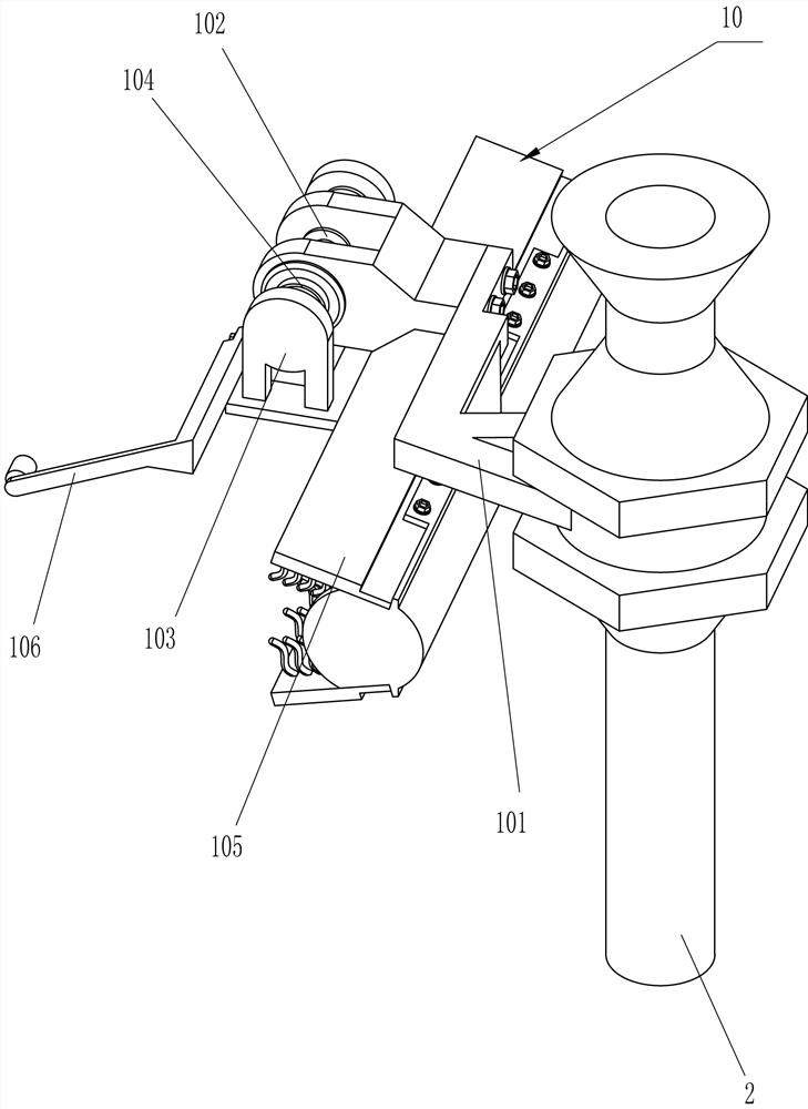
[0033] like Figure 1-5 As shown, an intelligent auxiliary dip soldering processing equipment for circuit boards includes a base 1, a heating chamber 1001 is installed on the upper side of the base 1, and support rods 2 are connected to the left and right sides in front of the upper side of the base 1 by bolts, The upper side of the support rod 2 is connected with the support frame 3 by bolts, the upper side of the support frame 3 is connected with the top frame 4 by bolts, and the bottom of the rear side of the top frame 4 and the rear of the upper side of the base 1 are connected with a fixed rod 5 by bolts. A mounting frame 6 is connected between the fixing rods 5 by bolts. A displacement device 7 is arranged on the front side of the mounting frame 6. The displacement device 7 is used for left and right movement and up and down movement. Connected with the displacement device 7, the propulsion device 8 is used for left and right propulsion, the up and down moving part of th...

Embodiment 2

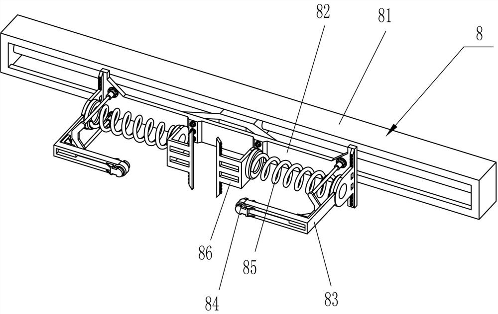
[0036] like Image 6 As shown, the displacement device 7 includes a first moving pair 71, the upper and lower sides of the front side of the mounting frame 6 are connected with a first moving pair 71 by bolts, and a moving plate 72 is connected between the moving parts of the first moving pair 71 by bolts, The moving plate 72 is connected with the propulsion device 8 , the front side of the moving plate 72 is connected with a second moving pair 73 through bolts, the sweeping device 9 is connected with the moving part of the second moving pair 73 , and the second moving pair 73 is provided with a first elastic member 74, the first elastic member 74 is a straight spring.

[0037] During the operation of the above embodiment, when the propulsion device 8 moves left and right, the propulsion device 8 will drive the moving plate 72 to move left and right through the first moving pair 71, thereby driving the sweeping device 9 to move left and right, and the sweeping device 9 is abou...


PUM


Abstract

The invention relates to circuit board dip soldering equipment, in particular to intelligent auxiliary dip soldering processing equipment for a circuit board. According to the intelligent auxiliary dip soldering processing equipment for the circuit board, a tin paste pool is automatically and rapidly cleaned, the surface layer of the tin paste pool is thoroughly cleaned, the cleaning process is automatically carried out, and the auxiliary working capacity is improved. According to the technical scheme, the intelligent auxiliary dip soldering processing equipment for the circuit board comprises a base, a heating chamber, supporting rods and the like, the heating chamber is installed on the upper side of the base, and the supporting rods are fixedly connected to the two sides of the front portion of the upper side of the base. According to the dip soldering device, the scraping and sweeping plate is driven by the first electric sliding rail to remove impurities of tin paste in the heating chamber, so that the tin paste in the heating chamber can be automatically cleaned, impurities on the surface of the tin paste are scraped, the defect that a scraper needs to be manually held for cleaning in traditional dip soldering work is overcome, the convenience of dip soldering work can be improved, and the working efficiency is improved. And manual operation steps are reduced.

Description

technical field [0001] The invention relates to a circuit board dip-soldering equipment, in particular to an intelligent auxiliary dip-soldering processing equipment for a circuit board. Background technique [0002] In the current dip soldering operation of the circuit board, it is necessary to manually operate the circuit board on the tin slurry pool, and it is also necessary to manually maintain the purity of the surface of the tin slurry pool, because in the exposed tin slurry pool above, there will be many External dust or magazines fall into the tin slurry pool, resulting in floating particulate impurities on the surface of the tin slurry pool, tin-containing impurity particles that cannot be melted due to condensed impurities, oxidized floaters or other impurities, if the tin slurry pool is not kept clean at all times , it is easy to make the circuit board have the disadvantages of point leakage during dip welding, and lead to the existence of magazines at the welding...

Claims


Application Information

Patent Timeline
Patent Type & Authority Applications(China)
IPC IPC(8): B23K3/00B23K3/08H05K3/34
CPCB23K3/00B23K3/08H05K3/34
Inventor 丁宏灿
Owner 丁宏灿
Why Eureka
Try Eureka