Textile fabric drying equipment for spinning

A technology for drying equipment and textile fabrics, which is applied in the direction of textile material equipment configuration, textile material processing, textiles and papermaking, etc., and can solve problems such as textile fabrics for a long time

Inactive Publication Date: 2021-01-05
成都迅仕达网络科技有限公司
View PDF0 Cites 0 Cited by
  • Summary
  • Abstract
  • Description
  • Claims
  • Application Information

AI Technical Summary

Problems solved by technology

[0003] At present, there is a kind of drying equipment for textile fabrics for textile use. When the drying equipment dries the textile fabrics, the moisture on the textile fabrics is evaporated to form water vapor that floats up to contact with the upper inner wall of the drying equipment, so that the water The steam condenses into water droplets, which cause the water droplets to fall under the action of gravity and drip back onto the textile fabric, resulting in a long drying time for the textile fabric

Method used


Image

  • Textile fabric drying equipment for spinning
  • Textile fabric drying equipment for spinning
  • Textile fabric drying equipment for spinning

Examples


Embodiment 1

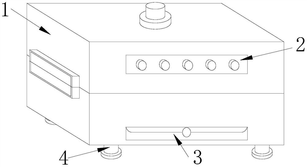
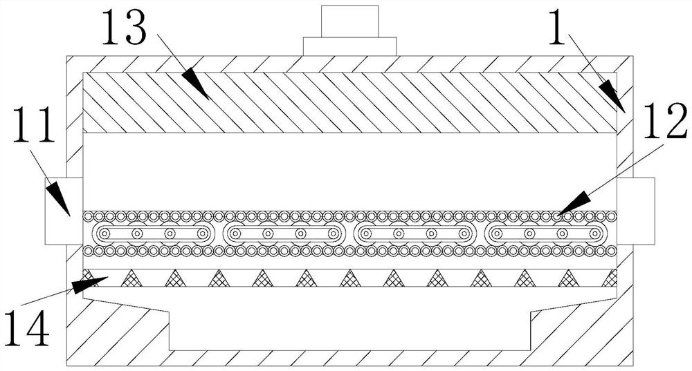
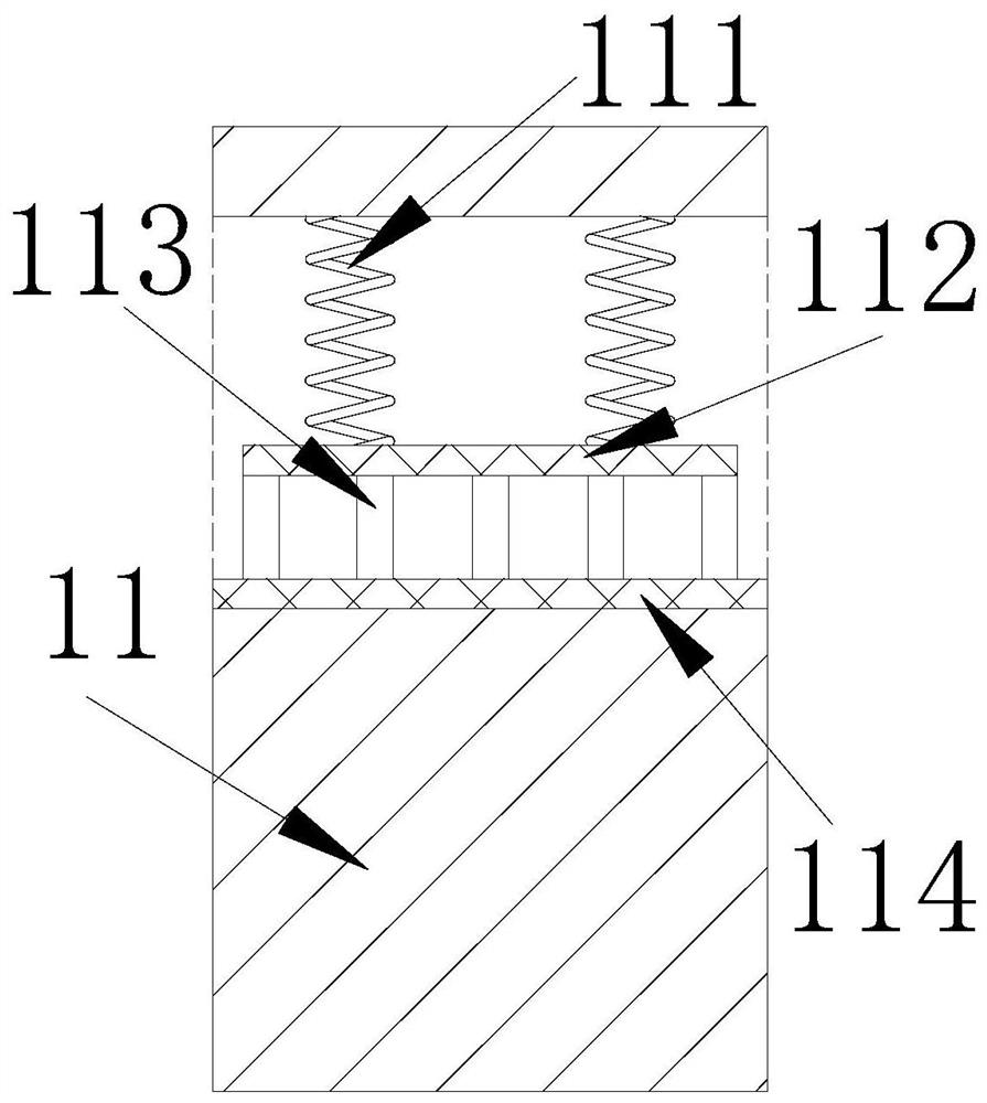
[0029] The present invention provides a textile cloth drying equipment for textile use, the structure of which comprises a drying box 1, a control panel 2, a cleaning tank 3, and a support foot 4, the control panel 2 is embedded in the front side of the drying box 1, and the The cleaning tank 3 is connected to the front side of the drying box 1 through movable engagement, and the supporting feet 4 are connected to the bottom of the drying box 1 by welding. 13. The heating sheet 14, the feed plate 11 is fixed on the left and right sides of the drying box 1, the guide belt 12 is connected to the interior of the drying box 1 by bolts and is located between the two feed plates 11, the The deflector 13 is connected to the top of the drying box 1 by welding, and the outer periphery of the heating sheet 14 is embedded in the inner wall of the drying box 1 and is located directly below the guide belt 12. There are two material-passing plates 11, and the guide belt The upper surface of...

Embodiment 2

[0035]The present invention provides a textile cloth drying equipment for textile use, the structure of which comprises a drying box 1, a control panel 2, a cleaning tank 3, and a support foot 4, the control panel 2 is embedded in the front side of the drying box 1, and the The cleaning tank 3 is connected to the front side of the drying box 1 through movable engagement, and the supporting feet 4 are connected to the bottom of the drying box 1 by welding. 13. The heating sheet 14, the feed plate 11 is fixed on the left and right sides of the drying box 1, the guide belt 12 is connected to the interior of the drying box 1 by bolts and is located between the two feed plates 11, the The deflector 13 is connected to the top of the drying box 1 by welding, and the outer periphery of the heating sheet 14 is embedded in the inner wall of the drying box 1 and is located directly below the guide belt 12. There are two material-passing plates 11, and the guide belt The upper surface of ...


PUM


Abstract

The invention discloses textile fabric drying equipment for spinning. The equipment structurally comprises a drying box, a control panel, a cleaning groove and supporting legs, the control panel is fixedly embedded at the front side of the drying box, the cleaning groove is movably connected to the front side of the drying box in a clamped manner, and the supporting legs are connected to the bottom of the drying box in a welded manner. The equipment has the beneficial effects that when the drying equipment is used, a pressure spring pushes a positioning plate downwards to enable an extrusion plate to extrude textile fabric, so that the textile fabric does not contain excessive moisture and is convenient to dry, a brush strip brushes the textile fabric to prevent dust adhered to the textilefabric from being solidified on the surface of the textile fabric after drying, moisture in the textile fabric is evaporated into water vapor through heat generated by a heating piece, the water vapor rushes to the two walls of a flow guide groove along a limiting plate to form water drops, a motor is started to drive a rotating rod to rotate continuously, a rotating plate and a water absorptionplate rub the inner wall of the flow guide groove continuously to adsorb the formed water drops, and therefore the water drops are prevented from falling back to the textile fabric.

Description

technical field [0001] The invention relates to the field of textiles, in particular to a textile cloth drying device for textiles. Background technique [0002] Textile fabric is an indispensable item in our daily life. In order to prevent the color of the textile fabric from being monotonous, it needs to be washed and dyed. The dyed fabric is dried by a drying equipment, and the drying equipment is used for heating. The temperature of the drying chamber rises, thereby evaporating the moisture on the textile fabric after washing, so as to prevent the moisture remaining on the textile fabric from affecting the dyeing of the textile fabric. [0003] At present, there is an existing textile fabric drying equipment for textile use. When the drying equipment dries the textile fabric, the moisture on the textile fabric is evaporated to form water vapor that floats up to contact with the upper inner wall of the drying equipment, so that the water The steam condenses into water dr...

Claims


Application Information

Patent Timeline
Patent Type & Authority Applications(China)
IPC IPC(8): D06B15/00D06B23/00D06B23/20D06G1/00
CPCD06B15/00D06B15/005D06B23/00D06B23/20D06G1/00
Inventor 熊建洪
Owner 成都迅仕达网络科技有限公司
Why Eureka
Try Eureka