
Shallow pile jacket structure for offshore booster station

An offshore booster station and jacket technology, which is applied in underwater structures, infrastructure engineering, hydraulic engineering and other directions, can solve the problems of the jacket's low anti-overturning and anti-slip capabilities, poor reliability of grouting connection sections, and pile foundation resistance. Low tensile bearing capacity and other problems, to achieve the effect of being conducive to anti-overturning stability, reducing uneven settlement, and improving vertical bearing capacity

Pending Publication Date: 2020-07-28
POWERCHINA HUADONG ENG COPORATION LTD
View PDF0 Cites 1 Cited by
  • Summary
  • Abstract
  • Description
  • Claims
  • Application Information

AI Technical Summary

Problems solved by technology

[0007] The purpose of the present invention is to provide a shallow pile jacket structure for offshore booster stations, to solve the problem of jacket foundation problems in traditional offshore booster stations for sites with large water depth, shallow overburden and thick silt on the seabed surface. The pile foundation has low tensile bearing capacity, large horizontal deformation, low anti-overturning and anti-slip capabilities of the jacket during construction, large uneven settlement, and poor reliability of the grouting connection section. Therefore, the present invention adopts the following technical solutions:

Method used


Image

  • Shallow pile jacket structure for offshore booster station
  • Shallow pile jacket structure for offshore booster station
  • Shallow pile jacket structure for offshore booster station

Examples


Embodiment Construction

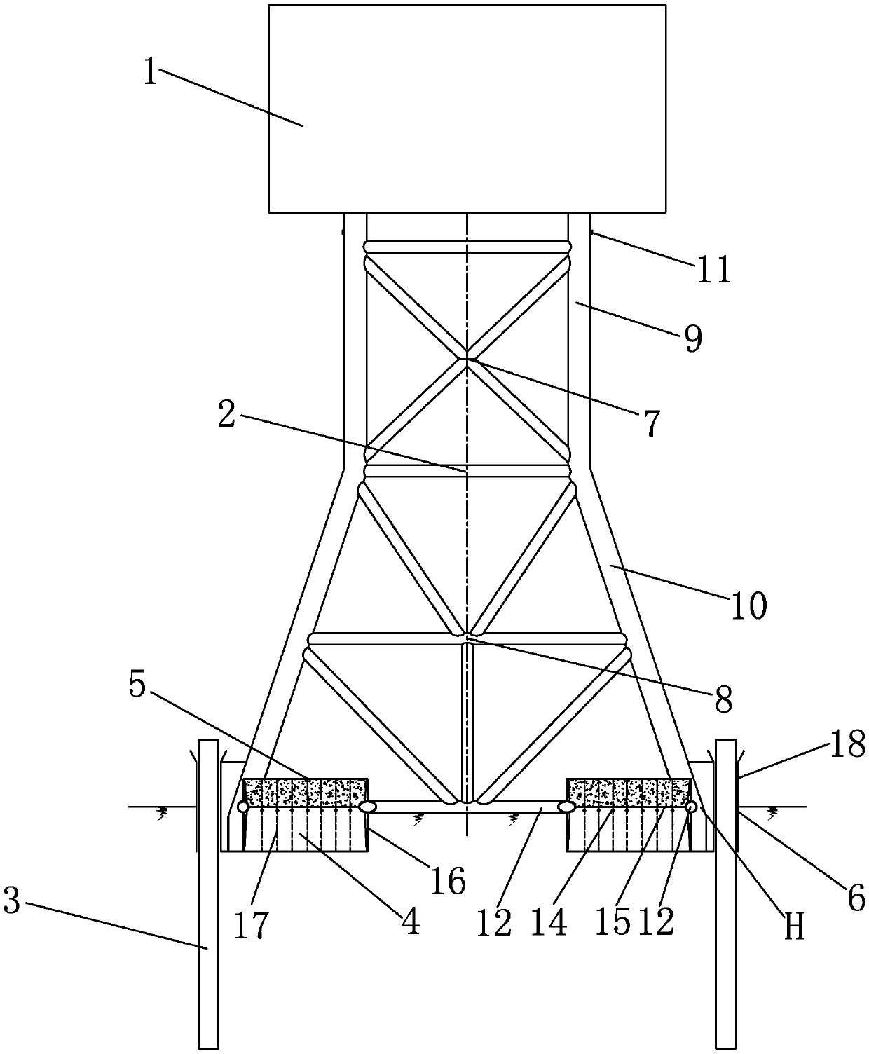
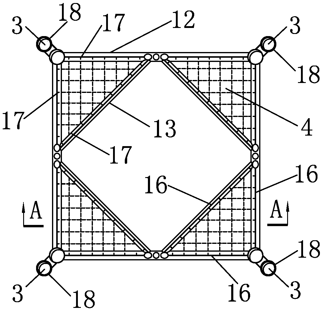
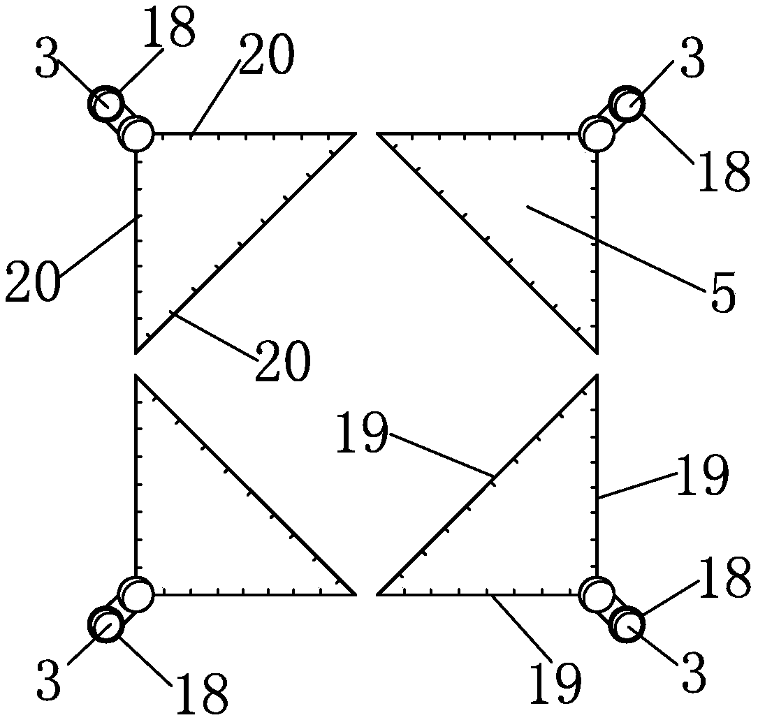
[0031] Such as Figure 1~Figure 5 As shown, this embodiment is an offshore step-up station with a capacity of 300MW. The sea area where the offshore step-up station is located has a water depth of 40m, and there is a relatively thick silt layer on the surface of the seabed cover. The upper platform 1 of the offshore step-up station is an integrally closed structure, and the overall construction is completed on land, and then transported to the sea area of ​​the wind farm for hoisting.

[0032] Such as Figure 1~Figure 5 As shown, in this embodiment, a shallow pile jacket structure used for offshore booster stations includes a large foot jacket 2, a non-rock-socketed short pile 3, an anti-skid box 4, a ballast box 5 and a pressure-resistant type Grouting section 6.

[0033] Such as figure 1 As shown, the large foot jacket 2 is made up of the jacket 7 of the above water part and the jacket 8 of the underwater part. The main conduit 9 of the jacket 7 on the water surface is v...


PUM


Abstract

The invention provides a shallow pile jacket structure for an offshore booster station. The shallow pile jacket structure for the offshore booster station includes a pedestal foot jacket, non-rock-socketed short piles, an anti-sliding box, a ballast box and a compression grouting section; an area between a horizontal transverse brace and a horizontal diagonal brace of the four corners at the bottom of the pedestal foot jacket is provided with the anti-sliding box, and the anti-sliding box is inserted into mud on the surface of the sea bottom; the ballast box is arranged on the upper part of the anti-sliding box; the outer sides of the bottom of the pedestal foot jacket are provided with the four or more non-rock-socketed short piles, the non-rock-socketed short piles are driven into a rockfoundation face under a seabed, due to high end bearing capacity of the rock foundation surface, compression bearing capacity of the short piles is high, and uplift bearing capacity of the short piles is low; a main guiding pipe and a pile guiding pipe of the pedestal foot jacket are inserted into the mud; and the non-rock-socketed short piles are connected with the pile guiding pipe through thecompression grouting section. According to the shallow pile jacket structure, problems that traditional offshore booster station foundations are low in tensile bearing capacity of pile foundations, serious in horizontal deformation, low in anti-dumping and anti-sliding capacity of a jacket during construction, large in uneven settlement, and poor in reliability of the grouting section are solved.

Description

technical field [0001] The invention relates to a shallow pile jacket structure used in an offshore booster station, which is suitable for the field of offshore wind power generation. Background technique [0002] The offshore booster station is the booster, power distribution and control center of the offshore wind farm. The offshore booster station is generally equipped with various electrical equipment such as main transformers, high and low voltage power distribution cabinets, GIS, and communication relay protection equipment. The offshore booster station will After the power generated by all offshore wind turbines is collected, the voltage is boosted by the main transformer, and then sent to land through high-voltage submarine cables. [0003] The foundation of the offshore booster station is a facility that fixes the entire superstructure of the offshore booster station on the seabed. In addition to bearing the entire weight of the superstructure, the foundation of the...

Claims


Application Information

Patent Timeline
IPC IPC(8): E02B17/00E02B17/02
CPCE02B17/00E02B17/02E02B17/0008E02B2017/0056
Inventor 吴关叶方滔赵生校戚海峰俞华锋张栋梁孙震洲汤群益袁建平贾献林吕国儿王永发陶安徐小龙
Owner POWERCHINA HUADONG ENG COPORATION LTD
Learn More