
Three-dimensional point cloud target detection method

A target detection and 3D point cloud technology, applied in the field of computer vision, can solve problems such as excessive differences in point cloud representation forms, poor detection performance of long-distance and occluded point clouds, and invisibility

Active Publication Date: 2020-07-24
FUDAN UNIV
View PDF7 Cites 17 Cited by
  • Summary
  • Abstract
  • Description
  • Claims
  • Application Information

AI Technical Summary

Problems solved by technology

[0004] 1. The point cloud data of the 3D scene is obtained through the lidar, depth camera and binocular camera for target detection, but as the distance from the target to the depth sensor increases, the density of the point cloud will drop sharply, resulting in a huge density change. In addition, due to occlusion, some parts of the target may be invisible, resulting in a huge distribution gap between the target point cloud of the same category. In summary, due to the large difference in the representation of the point cloud, the 3D target detection results are prone to errors;
[0005] 2. The current target detection algorithms are usually based on deep neural networks. With the continuous development of artificial intelligence, deep neural networks are widely used in most tasks in the field of autonomous driving due to their high precision and robustness. The performance of neural networks in the field of 2D target detection far exceeds other types of algorithms, because 2D images do not have the problems of sparsity and irregularity of 3D point clouds, but it is precisely because of the representation problems of these 3D point clouds that lead to The 3D object detection algorithm has poor detection performance for long-distance and occluded point clouds

Method used


Image

  • Three-dimensional point cloud target detection method

Examples


Embodiment Construction

[0021] The following will clearly and completely describe the technical solutions in the embodiments of the present invention with reference to the accompanying drawings in the embodiments of the present invention. Obviously, the described embodiments are only some, not all, embodiments of the present invention. Based on the embodiments of the present invention, all other embodiments obtained by persons of ordinary skill in the art without making creative efforts belong to the protection scope of the present invention.

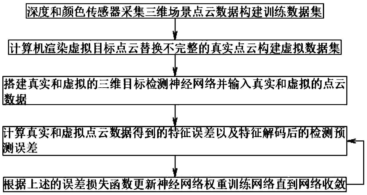
[0022] see figure 1 , the present invention provides a technical solution: a method for detecting a three-dimensional point cloud target, comprising the following steps:

[0023] S1. Obtain the point cloud information (including three-dimensional coordinates and color) of the three-dimensional scene through the depth sensor (the depth sensor is a laser radar, RGB-D depth camera, and one of the double-sided cameras to obtain the three-dimensional coordinates an...


PUM


Abstract

The invention discloses a three-dimensional point cloud target detection method. The method comprises the following steps: point cloud information of a three-dimensional scene is obtained through a depth sensor and an image sensor to serve as a training data set of a neural network; the point cloud of the target in the scene due to visual angle shielding and long-distance missing is complemented by utilizing a target point cloud model rendered by a computer; two three-dimensional target detection networks are constructed as a virtual training data set, one three-dimensional target detection network being used for inputting real data and the other three-dimensional target detection network being used for inputting virtual data, and the real three-dimensional scene point cloud data and the virtual three-dimensional scene point cloud data are respectively input into respective point cloud feature coding networks for feature extraction; the association perception process is simulated and applied to the deep neural network, and the incomplete point cloud information coding feature domain in the real scene is migrated to the virtual complete point cloud information coding feature domainthrough the transfer learning technology so that the neural network is enabled to actively associate the incomplete point cloud to the complete point cloud.

Description

technical field [0001] The invention relates to the technical field of computer vision, in particular to a method for detecting a three-dimensional point cloud target. Background technique [0002] Today, 3D object detection is the most widely used and important in autonomous driving and robot scene perception. [0003] But, there is following shortcoming in prior art: [0004] 1. The point cloud data of the 3D scene is obtained through the lidar, depth camera and binocular camera for target detection, but as the distance from the target to the depth sensor increases, the density of the point cloud will drop sharply, resulting in a huge density change. In addition, due to occlusion, some parts of the target may be invisible, resulting in a huge distribution gap of the target point cloud of the same category. In summary, due to the large difference in the representation form of the point cloud, the 3D target detection results are prone to errors; [0005] 2. The current tar...

Claims


Application Information

Patent Timeline
Patent Type & Authority Applications(China)
IPC IPC(8): G06K9/00G06N3/04G06N3/08G06T7/50G06T7/90
CPCG06T7/90G06T7/50G06N3/08G06T2207/10028G06V20/64G06V2201/07G06N3/045
Inventor 冯建峰杜量
Owner FUDAN UNIV
Learn More