
Mechanical interlocking type pressure ventilation pipe automatic drainage device

A technology of automatic water discharge and mechanical interlocking, which is applied in the direction of valve operation/release device, valve device, mechanical equipment, etc. It can solve the problems of water accumulation in the air pressure pipe and failure to discharge water in time, to simplify the circuit and eliminate the loss of pressure. , the effect of improving stability and reliability

Pending Publication Date: 2020-07-24
SHANXI LUAN ENVIRONMENTAL ENERGY DEV CO LTD WANGZHUANG COAL MINE
View PDF0 Cites 0 Cited by
  • Summary
  • Abstract
  • Description
  • Claims
  • Application Information

AI Technical Summary

Problems solved by technology

The current water storage mechanism needs to manually open and close the valve to release water, but often due to the negligence of workers, the water is not released in time. When the water level rises to the position of the pressure air pipe, the water discharge process will be interrupted, causing water accumulation in the pressure air pipe again.

Method used


Image

  • Mechanical interlocking type pressure ventilation pipe automatic drainage device
  • Mechanical interlocking type pressure ventilation pipe automatic drainage device
  • Mechanical interlocking type pressure ventilation pipe automatic drainage device

Examples


Embodiment Construction

[0019] In order to have a clearer understanding of the technical features, purposes and effects of the present invention, the specific implementation manners of the present invention will now be described in detail with reference to the accompanying drawings.

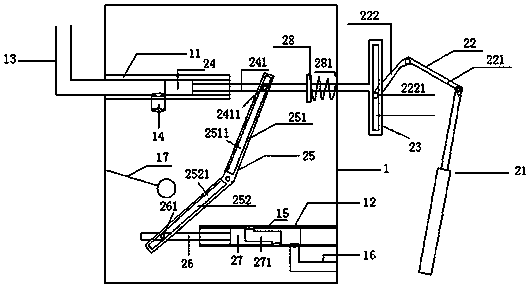
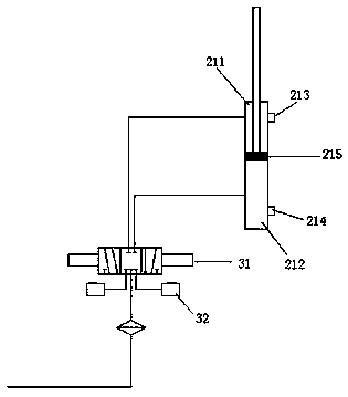
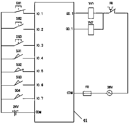
[0020] Such as figure 1 As shown, the mechanical interlocking type pressure air pipe automatic water discharge device of the present invention includes a water storage mechanism 1, a drainage piston mechanism 2, a pneumatic control mechanism 3 and a cylinder electric control mechanism 4;

[0021] The water storage mechanism 1 is a cubic container. On the side wall of the water storage mechanism 1 near the top and bottom, a water inlet pipe sleeve 11 and a water discharge pipe sleeve 12 extending inwardly are arranged, and a water inlet pipe is arranged in the water inlet pipe sleeve 11. 13. The water inlet pipe 13 enters the water inlet pipe sleeve 11 through the side wall from the outside of the water storage mechanism...


PUM


Abstract

The invention relates to a mechanical interlocking type pressure ventilation pipe automatic drainage device. A pneumatic control system is utilized to drive a piston and a pipe hole in a water storagemechanism to move, the movement of a valve element and the piston is utilized to block and stagger drainage holes, the working principle that one of the piston on the top of the water storage mechanism and the valve element at the bottom of the water storage mechanism completely blocks the corresponding drainage hole, and the other can begin to expose the corresponding drainage hole is utilized,mechanical interlocking of the piston and the valve element is achieved, and the loss, caused by drainage of the water storage mechanism, of the pressure of a pressure ventilation pipe is completely eradicated. The PLC control is adopted, circuits are simplified, and the stability and the reliability of the circuits are improved. According to the mechanical interlocking type pressure ventilation pipe automatic drainage device, a slider-crank mechanism is utilized to drive the piston and the valve element and transmit the acting force of an air cylinder and a spring. A three-position five-way solenoid valve is adopted to switch the stretching operation and the drawing operation of the air cylinder. Due to the fact that the three-position five-way solenoid valve can be immediately powered off through a reed switch on the air cylinder, and can be located at the neutral position, the phenomenon that due to the fact that a solenoid valve coil is energized for a long time, the coil emits heat and is burnt out is avoided, and the three-position five-way solenoid valve and a machine in a feeder switch are kept similar.

Description

technical field [0001] The invention relates to the technical field of mine safety, and more specifically relates to a mechanically interlocked automatic water discharge device for compressed air pipes. Background technique [0002] Pneumatic tools such as downhole jacks, air pumps, and pneumatic drills are all driven by the wind in the compressed air pipe. After the compressed air generated by the compressor enters the compressed air pipe, the moisture contained in the gas gradually condenses into water droplets and deposits in the pipe. Over time, the accumulated water in the pipeline will occupy a certain space, which will reduce the cross-sectional area of ​​the gas flowing through the pipeline, increase the resistance of the gas flow, and increase the pressure head loss of the gas. Excessive pressure head loss will result in insufficient air pressure of pneumatic tools, thereby reducing the torque of air pumps, air picks, and air drills, and affecting drainage, drillin...

Claims


Application Information

Patent Timeline
Patent Type & Authority Applications(China)
IPC IPC(8): F16K3/26F16K3/24F16K3/314F16K3/30F16K27/04F16K31/06F16K31/122F16K31/30F16K31/46F16K31/52F16L55/07E21F16/00
CPCF16K3/26F16K3/24F16K3/314F16K3/30F16K27/041F16K31/0603F16K31/0675F16K31/122F16K31/30F16K31/46F16K31/523F16L55/07E21F16/00
Inventor 李强李磊郜慧青荣乾坤郭宏杜梦远
Owner SHANXI LUAN ENVIRONMENTAL ENERGY DEV CO LTD WANGZHUANG COAL MINE
Learn More