
Coaxial-to-microstrip connector suitable for cavity filter and assembling method

A cavity filter and connector technology, applied in the microwave field

Active Publication Date: 2020-07-17
BEIJING INST OF RADIO METROLOGY & MEASUREMENT
View PDF1 Cites 3 Cited by
  • Summary
  • Abstract
  • Description
  • Claims
  • Application Information

AI Technical Summary

Problems solved by technology

A connector that realizes the lossless connection between the cavity filter and the microwave circuit microstrip transmission line, to solve the problem of lossless transmission between the microwave signal coaxial and the microstrip between the existing cavity filter and the circuit transmission line, and to ensure product integration Reduce the workload of debuggers and improve product consistency under the premise of accuracy

Method used


Image

  • Coaxial-to-microstrip connector suitable for cavity filter and assembling method
  • Coaxial-to-microstrip connector suitable for cavity filter and assembling method
  • Coaxial-to-microstrip connector suitable for cavity filter and assembling method

Examples


Embodiment 1

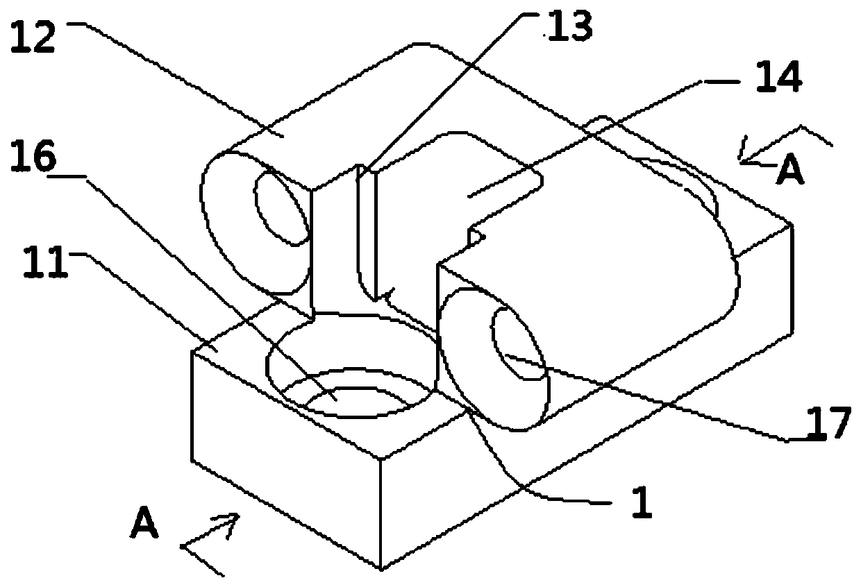
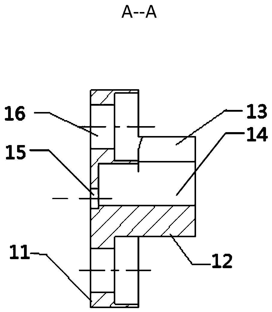
[0035] A coaxial-to-microstrip connector suitable for cavity filters provided in Embodiment 1, please refer to figure 1 and figure 2 As shown, including the base body 1, a microstrip cavity 14 is provided on one side of the base body 1, and an air transition cavity 15 penetrating to the other side of the base body 1 is opened at the end of the microstrip cavity 14 away from the opening, adding a section of the air transition cavity is beneficial to The standing wave at the connection between the cavity filter and the microwave circuit is improved, and at the same time, the insertion loss caused by the use of the cavity filter in the microwave circuit will be greatly reduced, thereby improving the overall performance of the integrated microwave circuit. The air transition cavity is located between the cavity filter insulation terminal and the microstrip cavity, and the impedance transformation characteristics between the coaxial and microstrip can be adjusted. The depth and di...

Embodiment 2

[0042] This embodiment 2 provides an assembly method for a coaxial-to-microstrip connector suitable for cavity filters. When using it, please refer to Figure 4 As shown, before installing the main structure (coaxial to microstrip connector), it is necessary to lay the microstrip line 4 in the microstrip cavity 14 of the main structure, and then install the main structure on the input of the cavity filter through the transverse mounting flange. The output end 3 is to make the inner conductor 7 of the insulated terminal of the cavity filter (hereinafter referred to as the inner conductor) lapped on the pre-laid microstrip line 4 in the microstrip cavity of the main structure, and the inner conductor and the main structure microstrip are connected by welding. The microstrip lines in the cavity 14 are connected together to realize electrical interconnection between the cavity filter and the microstrip lines. Finally, the cavity filter with the main structure installed is embedded...

Embodiment 3

[0048] Embodiment 3 provides test results of a microstrip-to-coaxial connector suitable for a coaxial-to-microstrip connector of a cavity filter.

[0049]


PUM


Abstract

The invention discloses a coaxial-to-microstrip connector suitable for a cavity filter and an assembling method, and relates to the connector technical filed. The coaxial-to-microstrip connector comprises a substrate capable of being simultaneously connected with the cavity filter and a microwave circuit, a microstrip cavity is formed at one side of the substrate, and an air transition cavity penetrating to the other side of the substrate is formed at one end, far away from an opening, in the microstrip cavity. By using the coaxial-to-microstrip connector, the impedance matching characteristicof the cavity filter at the coaxial-to-microstrip position in a microwave integrated circuit is ensured, the debugging workload of the debugging personnel is greatly reduced, at the same time, the consistency of products is ensured, and the working efficiency is improved.

Description

technical field [0001] The present application relates to the field of microwave technology, in particular to a coaxial-to-microstrip connector and an assembly method for a cavity filter. Background technique [0002] Cavity filter is a passive device used in frequency distribution and frequency selection in microwave system in electronic equipment system. It is widely used in frequency source, switching filter bank and other systems due to its advantages of large bandwidth and high isolation. Cavity filter is a two-port device, which also has important functions such as signal isolation and interference suppression. It is widely used in modern microwave and millimeter wave communication, satellite communication, remote sensing and radar technology and other systems. The quality of its performance directly affects the running quality of the whole system. [0003] The traditional method of using the cavity filter is to design the dual ports of the cavity filter as input and ...

Claims


Application Information

Patent Timeline
IPC IPC(8): H01P1/04H01P11/00
CPCH01P1/045H01P11/007
Inventor 李东亮宋旸仇冬梅宋子敬贾治国
Owner BEIJING INST OF RADIO METROLOGY & MEASUREMENT
Learn More