A glue riveting mixed assembly method and assembly structure of composite material lip and air inlet
A mixed assembly and air intake technology, which is applied in the direction of material gluing, combustion of the air intake of the power unit, connecting components, etc., can solve problems such as easy scratches on the composite material layer, inability to use nails, and excessively large bolt heads. , to achieve the effect of preventing galvanic corrosion, improving mechanical connection strength, reducing seam and step difference
- Summary
- Abstract
- Description
- Claims
- Application Information
AI Technical Summary
Problems solved by technology
Method used
Image

Examples
Embodiment 1
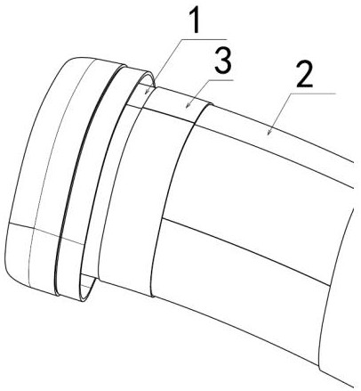
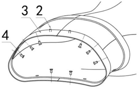
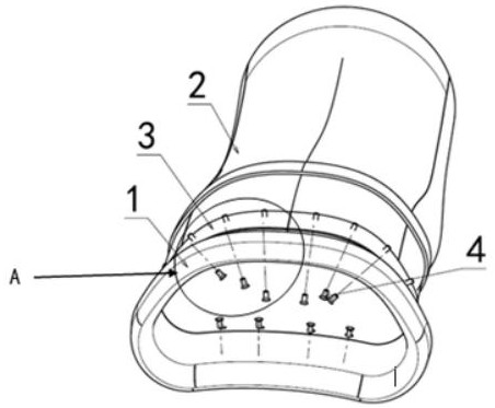
[0032] This embodiment provides a method for gluing and riveting hybrid assembly of the composite lip and the air inlet. The composite lip 1 and the composite air inlet 2, which are aligned with the aerodynamic surface of the inner cavity, are connected by the composite material arranged on the outer ring. The parts 3 are connected as a whole; the composite material lip 1 is connected to the composite material connecting part 3 through the normal temperature glue 5 and the countersunk rivet 4 at the same time, and the composite material inlet 2 is passed through the normal temperature glue 5 and the countersunk rivet at the same time 4 is connected with the composite connector 3.
[0033] The mixed assembly method of glue riveting specifically includes the following steps:
[0034] Step S100: brush a layer of room temperature glue 5 on the assembly surface outside the port of the composite air inlet 2;
[0035] Step S200: Partially overlap the composite material inlet duct 2 ...
Embodiment 2
[0049] In this embodiment, on the basis of Embodiment 1, the R-angle area where the curvature of the composite material lip 1 and the composite material inlet channel 2 changes greatly is only connected to the composite material connector 3 through room temperature glue 5, and no countersunk head is installed. Rivet 4. The non-R angle area of the composite material lip 1 and the composite material air inlet 2 is connected with the composite material connector 3 through the countersunk rivet 4; among them, the non-R angle area of the composite material lip 1 and the composite material air inlet 2 Refers to a flat area with small curvature changes.
[0050] On the one hand, the arrangement position of the countersunk rivets 4 avoids the area with the largest curvature change on both sides, and at the same time, the head of the countersunk rivets 4 is as flush as possible with the aerodynamic surface of the inner cavity. Usually, through strength calculation and analysis, a ...
Embodiment 3
[0056] On the basis of Embodiment 1 or Embodiment 2, this embodiment discloses a composite assembly structure of a composite material lip and an air inlet, including a composite material lip 1 and a composite material air inlet 2; The composite material lip 1 and the composite material inlet 2 are assembled together with a composite material connector 3 of the jacket; the composite material lip 1 and the composite material connector 3 are simultaneously connected by countersunk rivets 4 and room temperature glue 5; The composite material inlet channel 2 is connected with the composite material connector 3 through countersunk rivets 4 and room temperature glue 5 at the same time. At this time, the composite material lip 1 and the composite material inlet port 2 are terminated, that is, the composite material lip 1 and the composite material inlet port 2 have basically the same aerodynamic surface of the inner cavity, and there is no obvious mutation.
[0057] Further, the count...
PUM
| Property | Measurement | Unit |
|---|---|---|
| diameter | aaaaa | aaaaa |
Abstract
Description
Claims
Application Information
 - R&D
- Intellectual Property
- Life Sciences
- Materials
- Tech Scout
- Unparalleled Data Quality
- Higher Quality Content
- 60% Fewer Hallucinations
Browse by: Latest US Patents, China's latest patents, Technical Efficacy Thesaurus, Application Domain, Technology Topic, Popular Technical Reports.
© 2025 PatSnap. All rights reserved.Legal|Privacy policy|Modern Slavery Act Transparency Statement|Sitemap|About US| Contact US: help@patsnap.com