
Methods of producing high-strength metal tubular bars possessing improved cold formability

Active Publication Date: 2007-09-20
TENARIS CONNECTIONS
View PDF12 Cites 47 Cited by
  • Summary
  • Abstract
  • Description
  • Claims
  • Application Information

AI Technical Summary

Benefits of technology

[0009] One embodiment of the present invention overcomes at least some of the problems of previous methods by providing an ultra high-strength bar, such as a tube preferably made of steel, suitable for cold forming or bending, and methods for making the bar. Such a bar or tube, after it has been formed or bent into the desired shape, maintains mechanical properties such as strength and / or fatigue life and can be used in its desired application without further thermal processing. In one embodiment, a bar is manufactured to exhibit no or minimal cracking upon visual inspection after being formed or bent.
[0013] In a second step, the bar is subjected to one or more cold drawing operations. These drawing operations reduce the cross-section of the bar to predetermined final dimensions, including outer diameter and wall thickness, and are performed without heating the tube above room temperature. In additional benefit, the drawing operations also improve the surface quality of the bar, which serves to increases the fatigue resistance of the final part formed from the bar.

Problems solved by technology

Unfortunately, owing to their reduced load-bearing cross-section, considering materials with identical mechanical properties, metal tubular bars also fail at lower loads than solid tubular bars of equal diameter
Finally, the exterior surface of the tubular bar may be shot-peened to introduce a state of compressive stresses onto the surface which inhibits the growth of flaws under fatigue loadings which can lead to failure.
Often, though, the thermal stresses generated in the tubular bar during the quench distort the shape of the tubular bar, requiring time consuming and costly re-forming operations to return the tubular bar to its desired shape.
The above methods require considerable time and effort to produce a high strength tubular bar with the desired properties.

Method used


Image

  • Methods of producing high-strength metal tubular bars possessing improved cold formability
  • Methods of producing high-strength metal tubular bars possessing improved cold formability
  • Methods of producing high-strength metal tubular bars possessing improved cold formability

Examples


Embodiment Construction

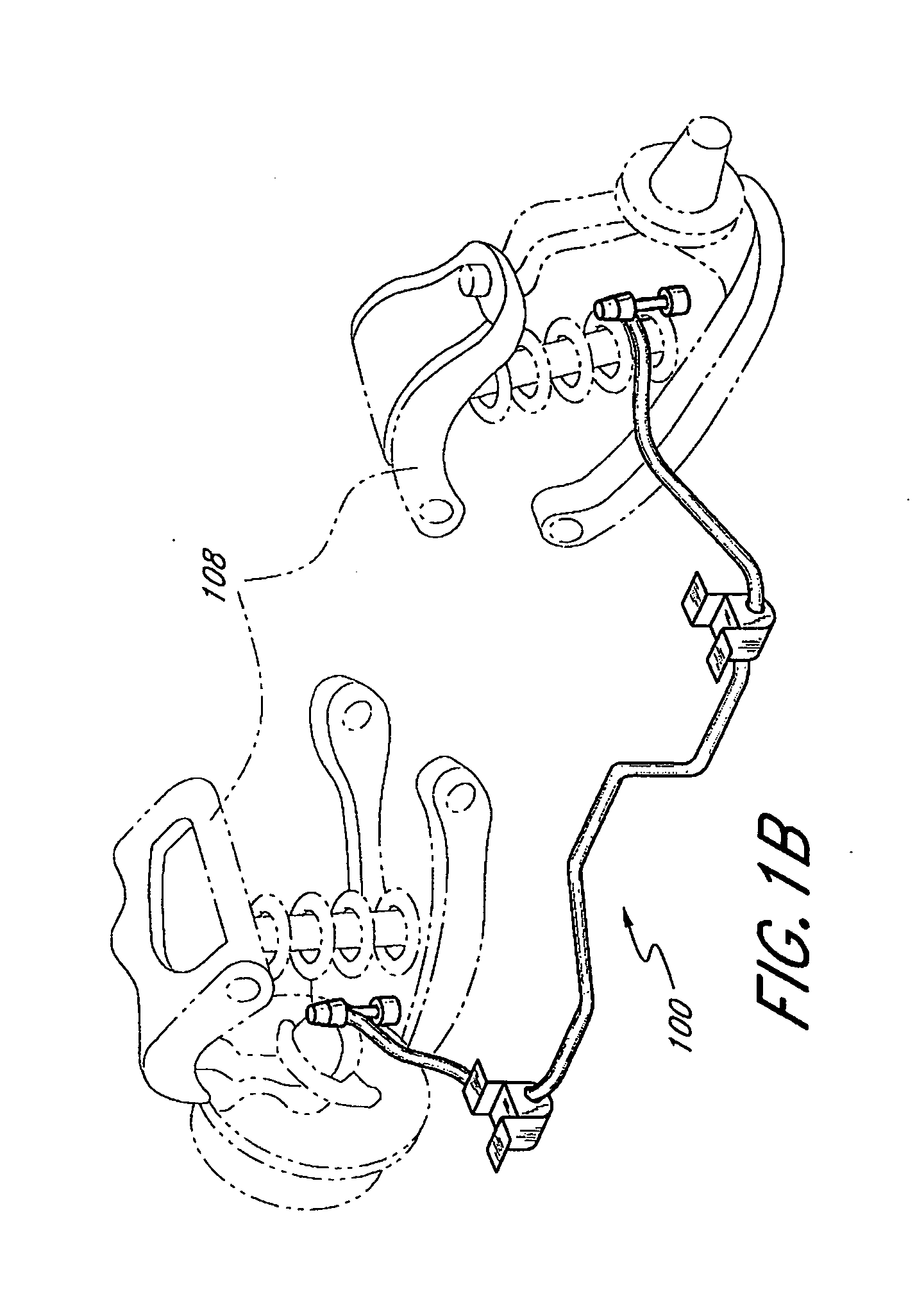
[0032] Embodiments of the present invention relate to the manufacture of stabilizer bars, especially for motor vehicles. However, the embodiments of the invention may be applied to the manufacture of any suitable tubular bar where high strength and formability are needed to obtain the final shape of the bar. Examples include, but are not limited to, structural frames and pipes for transmission of gas, liquids, and finely divided solids.

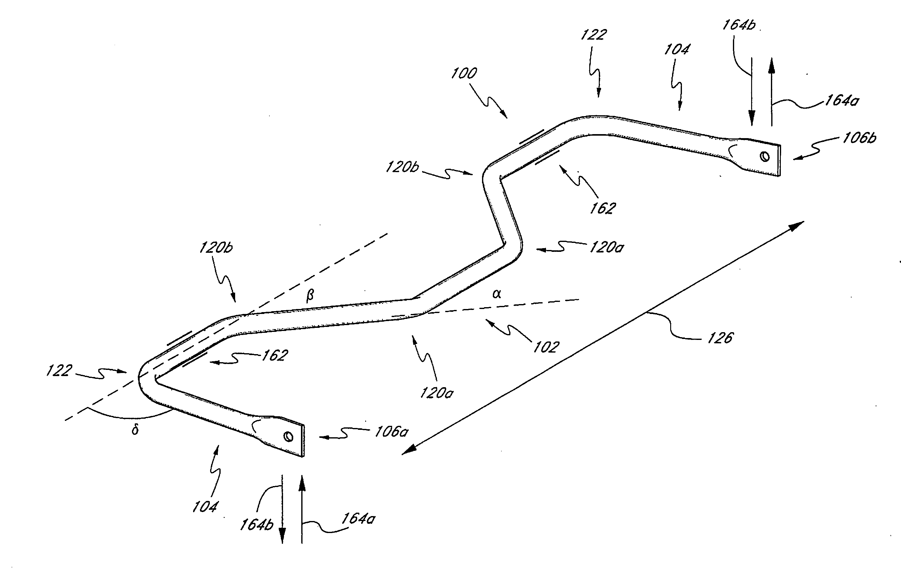
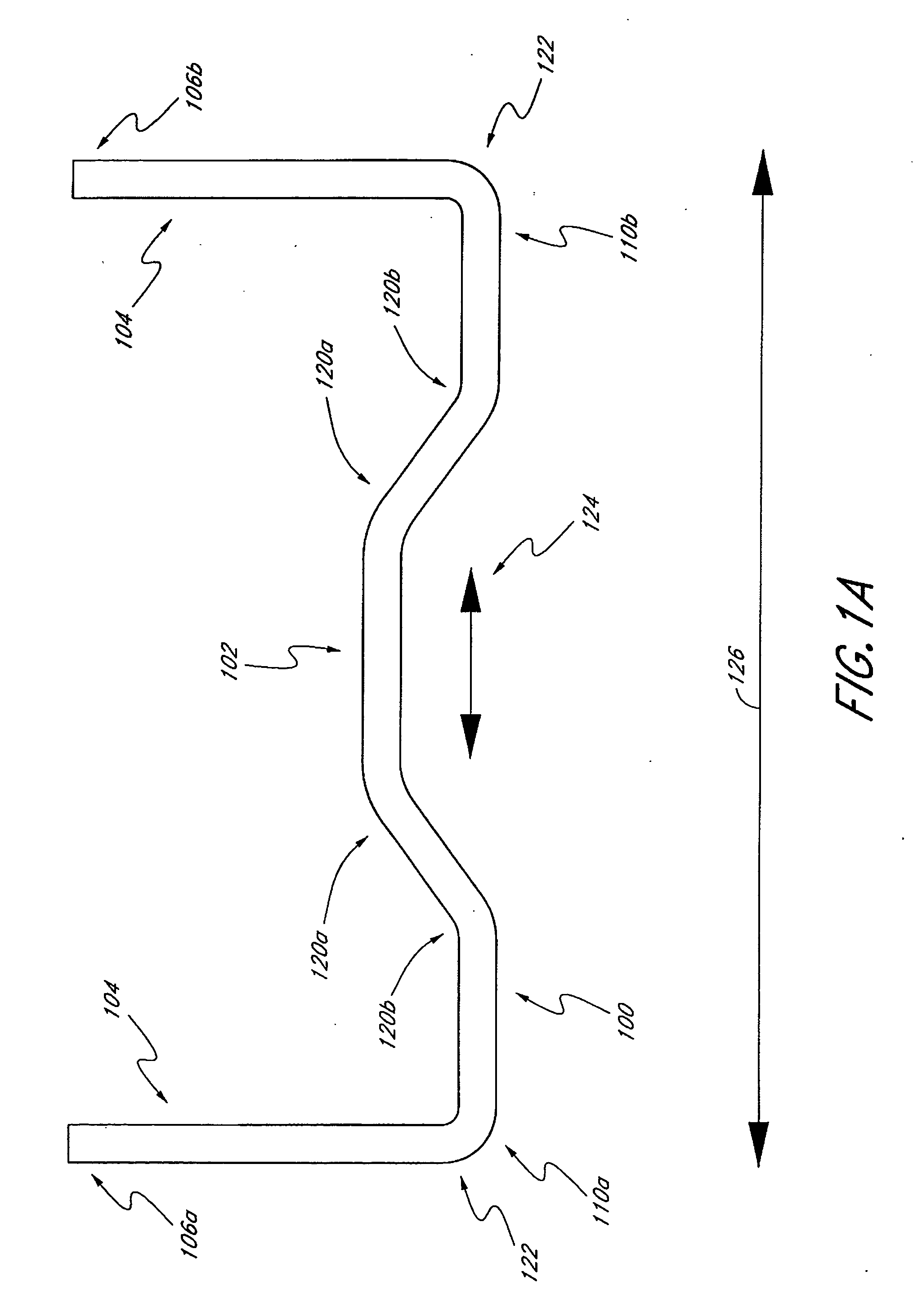
[0033] The term “bar” as used herein is a broad term and includes its ordinary dictionary meaning and also refers to a generally hollow, elongate member which may be straight or may have bends or curves and be formed to a predetermined shape, and any additional forming required to secure the formed tubular bar in its intended location. The bar may be tubular, having a substantially circular outer surface and inner surface, although other shapes and cross-sections are contemplated as well. As used herein, the term “tubular” refers to any elongate, hol...


PUM

PropertyMeasurementUnit
Temperatureaaaaaaaaaa
Fractionaaaaaaaaaa

Abstract

A method for producing a tubular bar, more particularly a stabilizer bar, is provided. The method comprises providing a tubular bar of desired size having an outer and inner surface, heating the bar to an elevated temperature, quenching the bar by application of a cooling fluid to the surfaces of the bar, and forming the tube to a desired shape without annealing. The method further provides for the composition of a high-strength, high formability carbon steel alloy to be used in conjunction with the method. Advantageously, the bar is formable without thermal processing subsequent to quenching. In this fashion, metal tubular bars, such as stabilizer bars, may be formed at reduced cost.

Description

BACKGROUND OF THE INVENTION [0001] 1. Field of the Invention [0002] The present invention relates generally to metal production and, in certain embodiments, relates to methods of producing metallic tubular bars having high strength and improved formability, and metal bars, particularly vehicular stabilizer bars, made by the same. [0003] 2. Description of the Related Art [0004] Metal tubular bars possess a number of advantages over solid bars when incorporated into engineered structures. For example, tubular bars are lighter than corresponding solid bars, of benefit to applications in which weight is a primary consideration. Automobile stabilizer bars are one example of the use of metal tubular bars. These bars are attached to an auto frame between the tires and function to counteract roll which occurs during turning, ensuring more even wear on tires and greater steering control when turning. Unfortunately, owing to their reduced load-bearing cross-section, considering materials with...

Claims


Application Information

Patent Timeline
IPC IPC(8): B60G21/05B21D9/04C21D9/08
CPCB60G21/055B60G21/0551B60G2200/144B60G2204/1222B60G2204/82Y10T428/12292B60G2204/8306B60G2206/012B60G2206/427C21D9/08B60G2204/8302
Inventor LOPEZ, EDGARDO OSCARCASERTA, LORENZO VITODESIMONE, HERNAN JUANSALAZAR, CUAUHTEMOC MARTINEZ
Owner TENARIS CONNECTIONS
Learn More