High-speed wire mill on-line accurate centering system and method

A high-speed wire rod and rolling mill technology, applied in the direction of guiding/positioning/alignment devices, etc., can solve the problem of being unable to quantitatively provide the centering accuracy of each stand, so as to improve the stability and accuracy of detection, improve the level of automation, and improve alignment. effect based on

Active Publication Date: 2020-07-17
BAOSHAN IRON & STEEL CO LTD
View PDF13 Cites 7 Cited by
  • Summary
  • Abstract
  • Description
  • Claims
  • Application Information

AI Technical Summary

Problems solved by technology

[0004] Although the above-mentioned methods can replace manual wire drawing and improve the alignment efficiency of high-speed rolling mills, they cannot quantitatively provide the alignment accuracy of each rack, and still rely on manual experience to adjust each rack

Method used


Image

  • High-speed wire mill on-line accurate centering system and method
  • High-speed wire mill on-line accurate centering system and method
  • High-speed wire mill on-line accurate centering system and method

Examples


Embodiment 1

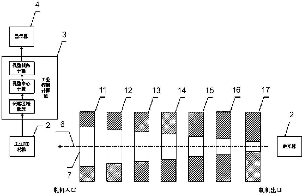
[0060] Such as figure 2 As shown, the industrial camera 3 uses a CCD industrial camera, the data processing module 4 uses an industrial computer, and its own display is used as the display module 5. The rolling mill group has seven stands 11, 12, 13, 14, 15, 16, and 17 for continuous rolling. Hole pattern 7 adopts the "round-ellipse-round" series.

[0061] (1) The calibration part is as follows:

[0062] A) Industrial camera adjustment

[0063] Turn on the laser 2 at the exit of the rolling mill, the laser 6 passes through the holes 7 of each rack and then falls into the lens of the industrial camera 3. Adjust the position of the industrial camera 3 so that the center of the light spot is at the center of the detection window. At this time, record the center position of the light spot (X 0 = 800, Y 0 =600), which is the center of alignment. Record the spot diameter as the original diameter D 0 = 20. Adjust the angle of the industrial camera 3 so that only the light spot can be se...

Embodiment 2

[0105] Such as Image 6 As shown, the industrial camera 3 uses a CCD industrial camera, the data processing module 4 uses an industrial computer, and its own display is used as the display module 5. The rolling mill group has five racks 11, 12, 13, 14, 15 for continuous rolling, and the pass type 7 uses "Ellipse-Circle-Ellipse" series.

[0106] (1) The calibration part is as follows:

[0107] A) Industrial camera adjustment

[0108] Turn on the laser 2 at the exit of the rolling mill, the laser 6 passes through the holes 7 of each rack 11-15 and then falls into the lens of the industrial camera 3. Adjust the position of the industrial camera 3 so that the center of the light spot is at the center of the detection window. At this time, record the center position of the light spot (X 0 = 800, Y 0 =600), which is the center of alignment. Record the spot diameter as the original diameter D 0 = 30. Adjust the angle of the industrial camera 3 so that only the light spot can be seen in t...


PUM


Abstract

The invention discloses a high-speed wire mill on-line accurate centering system and method. The system comprises a rack continuous rolling unit, and further comprises a laser device, an industrial camera, a data processing module and a display module, the laser device is arranged at the outlet position of the rack continuous rolling unit, the industrial camera is arranged at the inlet position ofthe rack continuous rolling unit, laser emitted from the interior of the laser device sequentially penetrates through all rack passes of the rack continuous rolling unit to reach the interior of a lens of the industrial camera, the industrial camera is used for capturing laser contour image information and contour image information of all the rack passes and sending the information to the data processing module, the data processing module is used for calculating off-center data of all racks according to the positions of laser spots and the conditions of all the rack passes and sending the data to the display module, and the display module is used for displaying the off-center data of all the racks in real time. According to the system and the method, the off-center numerical values of allthe racks can be given according to the recognition algorithm, the equipment centering basis can be accurately provided, and the rolling line centering precision and the automation level are improved.

Description

Technical field [0001] The invention relates to a high-speed wire rod mill centering technology, and more specifically, to a high-speed wire rod mill on-line accurate centering system and a centering method thereof. Background technique [0002] At present, the speed of high-speed wire rod rolling can reach more than 110m / s. At the same time, the distance between the racks of the high-speed wire production rough and medium rolling prestressing mill is relatively long, and the distance between the rough and medium rolling 1H-14V stands can reach A few tens of meters, which leads to a large deviation in actual field alignment. In order to ensure rolling stability and improve product quality, the center accuracy of each stand is required to be controlled at the 0.1mm level, which places high requirements on the centering technology of the wire roughing and middle rolling mill. [0003] In the traditional operating procedures, usually during the scheduled repair of the rolling line, t...

Claims


Application Information

Patent Timeline
Patent Type & Authority Applications(China)
IPC IPC(8): B21B39/14
CPCB21B39/14
Inventor 朱兴安谢超
Owner BAOSHAN IRON & STEEL CO LTD
Why Eureka
Try Eureka