A ccd camera refrigeration device based on thermoelectric refrigeration

A refrigeration device and thermoelectric refrigeration technology, applied in the field of photoelectric detection, can solve the problems of easy condensation, reaching sub-zero temperature, poor heat dissipation at the hot end, etc., and achieve the effect of low noise and strong signal output capability

Active Publication Date: 2021-10-26
XIAMEN UNIV
View PDF8 Cites 0 Cited by
  • Summary
  • Abstract
  • Description
  • Claims
  • Application Information

AI Technical Summary

Problems solved by technology

[0005] The present invention aims to solve the problems of poor heat dissipation at the hot end and easy condensation at the cold end of the existing thermoelectric refrigeration device, and further provides a CCD camera refrigeration device based on thermoelectric refrigeration

Method used


Image

  • A ccd camera refrigeration device based on thermoelectric refrigeration
  • A ccd camera refrigeration device based on thermoelectric refrigeration
  • A ccd camera refrigeration device based on thermoelectric refrigeration

Examples


specific Embodiment approach 1

[0028] Specific implementation mode one: as Figure 1~5 As shown, the CCD camera cooling device based on thermoelectric cooling in this embodiment includes a camera cooling housing, a cooling sealing system, an air cooling structure and a signal output device, and the cooling sealing system, air cooling structure and signal output device are all arranged in the camera cooling housing in vivo,

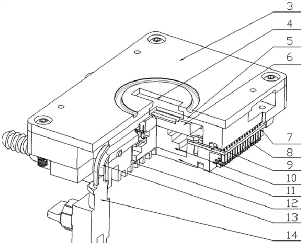
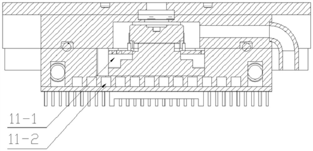
[0029] The refrigeration sealing system includes a refrigeration cavity 5 and a water-cooled plate 11. An optical window 4 is arranged at the center of the upper end of the refrigeration cavity 5. The refrigeration sealing system also includes a CCD signal adapter plate 7, a temperature sensor 12, a thermoelectric cooling sheet 10 and a water-cooled cover. Plate 16, CCD camera 6 is attached to the cold end of thermoelectric cooling plate 10, the upper end surface of water cooling plate 11 is concave cavity structure 11-1, and several flow channels 11-2 are processed on water cooling pla...

specific Embodiment approach 2

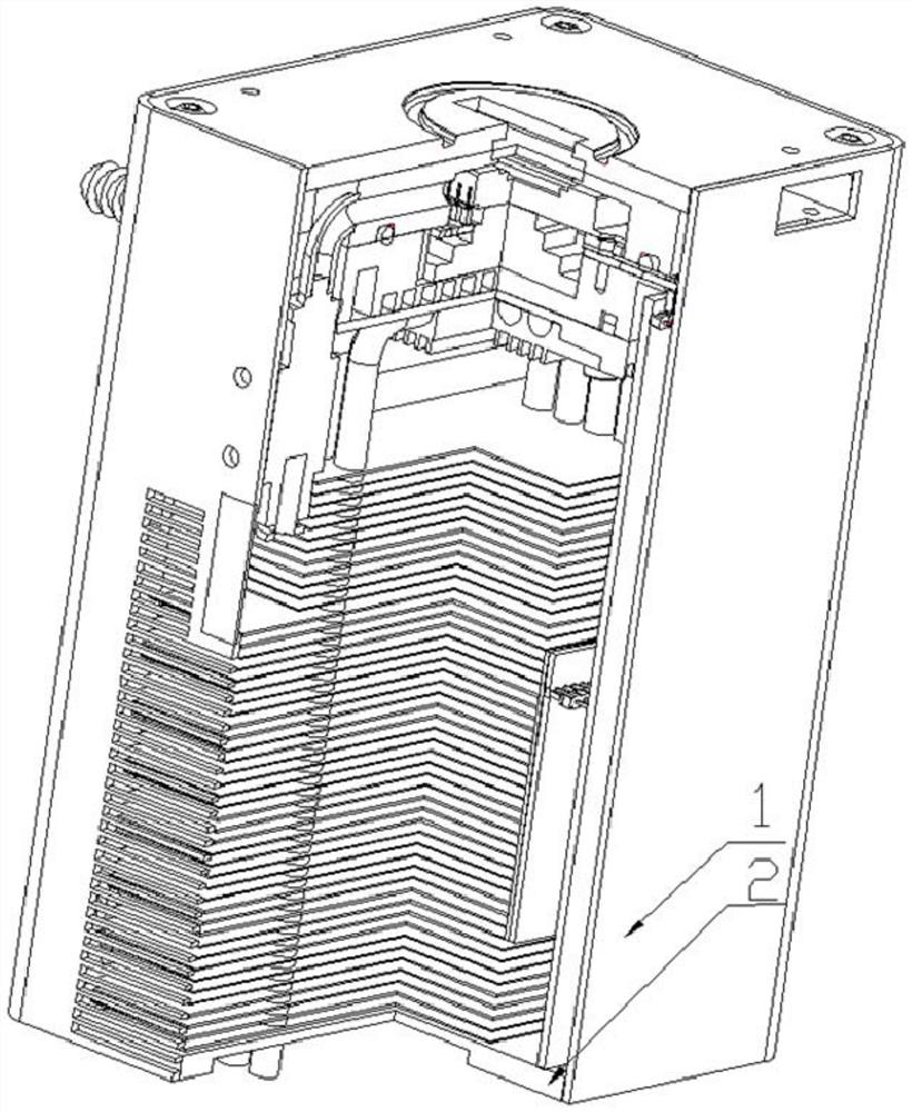
[0032] Specific implementation mode two: as figure 1 and figure 2 As shown, the camera refrigeration housing in this embodiment includes a packaging cylinder 1, a bottom plate 2 and an upper cover 3, the upper cover 3 is installed on the upper end surface of the packaging cylinder 1 by bolts, and the bottom plate 2 is installed on the lower end surface of the packaging cylinder 1 Above, the center of the upper cover 3 is processed with an optical window 4 .

[0033] In such a design, the packaging cylinder 1, the bottom plate 2 and the upper cover 3 realize the external packaging of the entire CCD camera cooling device. Other components and connections are the same as those in the first embodiment.

specific Embodiment approach 3

[0034] Specific implementation mode three: as figure 1 and figure 2 As shown, the optical window 4 of this embodiment is sealed with epoxy resin.

[0035]With such a design, since the cooling temperature inside the cooling chamber 5 reaches negative temperature, the cooling chamber must be sealed and the internal water vapor must be discharged. At the same time, the cooling chamber 5 is filled with nitrogen or vacuumized to prevent water vapor from being liquefied at low temperature and destroying the CCD. The camera works normally, and the TEC cooling effect is better in the vacuum environment. Other compositions and connections are the same as those in Embodiment 1 or 2.


PUM


Abstract

The invention discloses a CCD camera refrigeration device based on thermoelectric refrigeration, which relates to a camera refrigeration device. The invention solves the problems that the existing thermoelectric refrigeration device has poor heat dissipation at the hot end, refrigeration at the cold end reaches subzero temperature, and easy dew condensation. The hot end of the thermoelectric cooling plate is tightly attached to the concave cavity structure of the water-cooled plate. The other end of the CCD signal adapter board passes through the interlayer of the water-cooled plate and is located outside the water-cooled plate. The water-cooled plate and the CCD signal adapter plate are passed through epoxy The lower end of the water-cooling plate is sealed by welding the water-cooling cover plate, and the cooling cavity is filled with nitrogen or vacuumized; several heat pipe recesses are processed on the heat pipe seat, and the upper part of the heat pipe is installed in the corresponding heat pipe recess. The fan is installed in the On the side wall of the cooling fins, the lower part of the heat pipe passes through the cooling fins; the main control board is installed in the cooling housing of the camera and arranged parallel to the driving circuit board, and the driving circuit board is electrically connected to the main controlling board through pins. The invention is used for refrigeration of CCD cameras.

Description

technical field [0001] The invention relates to a camera cooling device, in particular to a thermoelectric cooling-based CCD camera cooling device, which belongs to the field of photoelectric detection technology. Background technique [0002] CCD (Charge Coupled Device) is an image sensor that converts optical signals into electrical signals, and is widely used in the field of photoelectric detection. CCD has high sensitivity, but because its dark current is particularly sensitive to temperature, the higher the temperature, the greater the dark current, resulting in larger dark current noise. Therefore, in order to improve the signal-to-noise ratio of optical signals, the CCD should be effectively reduced. In order to reduce the dark current of the working temperature, the dark current will be reduced by half for every 5-7°C drop. [0003] At present, CCD refrigeration mainly consists of thermoelectric refrigeration (TEC), liquid nitrogen refrigeration and thermomechanical...

Claims


Application Information

Patent Timeline
Patent Type & Authority Patents(China)
IPC IPC(8): G03B17/55F25B21/02F28D15/02
CPCG03B17/55F25B21/02F28D15/0275
Inventor 范贤光黄江尧王昕许英杰颜晓梅
Owner XIAMEN UNIV
Why Eureka
Try Eureka