
One-dimensional ultrasonic linear vibration turning device

A linear vibration and ultrasonic technology, used in turning equipment, auxiliary devices, large fixed members, etc., can solve the problems of complex equipment operation, reduce heat generation, reduce cutting force, etc., to improve dimensional accuracy, improve surface quality, reduce The effect of small shape errors

Inactive Publication Date: 2020-07-10
TAIYUAN UNIV OF TECH
View PDF9 Cites 1 Cited by
  • Summary
  • Abstract
  • Description
  • Claims
  • Application Information

AI Technical Summary

Problems solved by technology

Patent application number 201210024096.6 discloses an ultrasonic vibration cutting device, which is mainly composed of cutting blade, cutting tool head, lock nut, horn, and fixed chuck. The intermittent contact of the workpiece and chips reduces heat generation and cutting force, but it is not possible to select appropriate cutting process parameters such as edge inclination angle, leading angle, and rake angle according to different materials and working conditions to facilitate the process. cutting
In the patent application number 201821763680.2, a new type of bending-torsional composite vibration ultrasonic cutting device is disclosed. This device can also solve the problem of high-precision machining of certain mechanical parts in aerospace. The device proposes a single-directional vibration In actual machining, there is high-frequency friction between the flank of the tool and the machined surface of the workpiece, and the tool is subject to constantly changing alternating tension and compression stress during the cutting process, and the tool is prone to fatigue and chipping. Therefore, the compound vibration machining technology was studied. , can change the harmful friction between the rake face of the tool and the chip into a favorable cutting force, reduce the cutting temperature and cutting force, and improve the machining accuracy, but the operation of the equipment is complicated

Method used


Image

  • One-dimensional ultrasonic linear vibration turning device
  • One-dimensional ultrasonic linear vibration turning device
  • One-dimensional ultrasonic linear vibration turning device

Examples


Embodiment Construction

[0029] The following examples are used to illustrate the present invention, but are not intended to limit the scope of the present invention. Unless otherwise specified, the examples are all in accordance with conventional experimental conditions. In addition, for those skilled in the art, on the premise of not departing from the spirit and scope of the present invention, various modifications or improvements to the material components and dosages in these embodiments belong to the claims of the present invention. scope.

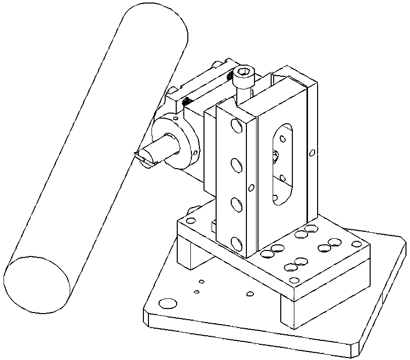
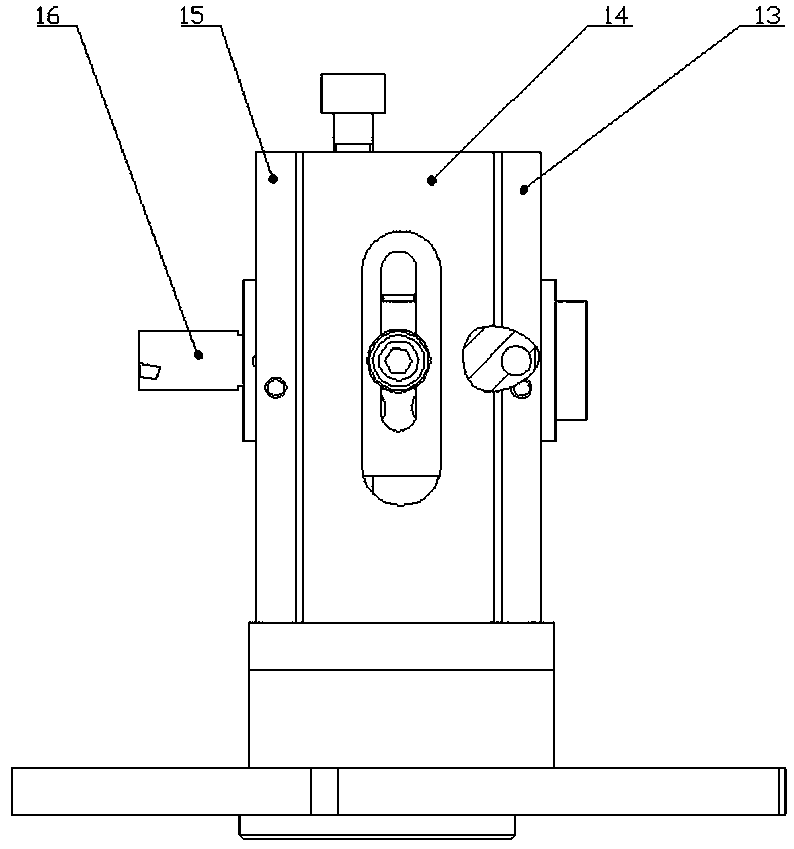
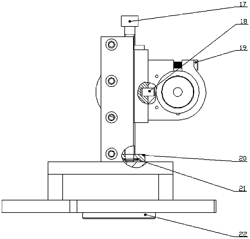
[0030] Such as Figure 1 to Figure 7 The shown one-dimensional ultrasonic linear vibration turning device includes a bottom plate 1, a clamping seat 7, a dovetail groove base 14 and a slider seat 23, wherein:

[0031] A central rotating block 22 is fixedly arranged below the core of the bottom plate 1, and a pit is arranged on the upper surface of the cutting station on the lathe, and the central rotating block 22 is correspondingly installed in the pit. ...


PUM


Abstract

The invention discloses a one-dimensional ultrasonic linear vibration turning device, and belongs to the technical field of turning devices. The technical problem of surface quality after cutting is solved. According to the solution scheme, a central rotating block is arranged below the center of a bottom plate, a pad block is detachably arranged above the bottom plate, a guide rail mounting plateis arranged across the pad block, a swallowtail slot left guide rail and a swallowtail slot right guide rail are arranged vertically above the guide rail mounting plate, and the left side and the right side of a swallowtail slot base are separately matched with the swallowtail slot left guide rail and the swallowtail slot right guide rail; and a sliding block seat is arranged on the outer side ofthe swallowtail slot base, a clamping seat is mounted on the outer side of the sliding block seat, a pin shaft is arranged between the assembly surface of the sliding block seat and the clamping seat, the clamping seat rotates around the pin shaft, and a through hole for clamping a variable amplitude rod assembly is formed in the clamping seat. The one-dimensional ultrasonic linear vibration turning device can improve the surface quality after cutting, and can select suitable cutting process parameters such as edge inclination angles, main deflection angles and front angles according to different materials and working conditions.

Description

technical field [0001] The invention belongs to the technical field of turning devices, and in particular relates to a one-dimensional ultrasonic linear vibration turning device. Background technique [0002] In today's all walks of life, the requirements for the machining accuracy and surface quality of precision mechanical parts are getting higher and higher. Some mechanical parts in aerospace require a dimensional accuracy of 10nm and a surface roughness of 1nm. More and more The mechanical parts of the machine are made of stainless steel, heat-resistant steel, titanium alloy, nickel alloy, aluminum-based silicon carbide, carbon fiber, glass and other difficult-to-machine materials, which bring great difficulties to the cutting process and put forward higher requirements for the cutting process technology. Require. Using traditional methods to process, the efficiency is very low or even impossible to process. Ultrasonic vibration machining can solve the machining proble...

Claims


Application Information

Patent Timeline
Patent Type & Authority Applications(China)
IPC IPC(8): B23B21/00B23B25/00B23Q1/25
CPCB23B25/00B23Q1/25
Inventor 董志国朱徐辉张鑫祺候张敏
Owner TAIYUAN UNIV OF TECH
Learn More