
Water penetrating cooling gas seal device

A water-penetrating cooling and air-sealing technology, applied in workpiece cooling device, drying gas arrangement, lighting and heating equipment, etc., can solve the problems of long construction time, unbalanced spinning head deformation, long processing cycle, etc. The effect of avoiding process and equipment accidents and short construction time

Pending Publication Date: 2020-07-10
XINXING DUCTILE IRON PIPES CO LTD
View PDF0 Cites 0 Cited by
  • Summary
  • Abstract
  • Description
  • Claims
  • Application Information

AI Technical Summary

Problems solved by technology

[0003] With the continuous upgrading of rolling mills and the maturity of rolling technology, the speed of finished products is steadily increasing. After the speed of finished products is increased, in order to ensure the low spinning temperature of rolled products, it is necessary to increase the water pressure in the raw water cooling box, resulting in the original water cooling box. The compressed air sealing device cannot completely seal the water due to the increase of the water pressure. In order to ensure the performance of the steel, the water pressure of the water-cooled box increases, which causes a large amount of cooling water to be taken out by the rolled material and left in the dry running tank, waiting for the next rolling After the material came over, due to the residual water in the dry running trough, the stacking of steel was hindered. In addition, the latest Danieli pinch rolls are air-cooled. Serious process and equipment accidents caused by deformation and imbalance. At present, the method commonly used in the industry is to replace the matching water cooling box, so that the water at the outlet of the delivery hole of the water cooling box will not be taken out in large quantities, but the investment is large and the processing The cycle is long, and the foundation and water-cooling control system need to be changed at the same time, and the construction time is long, resulting in long-term interruption of production

Method used


Image

  • Water penetrating cooling gas seal device
  • Water penetrating cooling gas seal device
  • Water penetrating cooling gas seal device

Examples


Embodiment Construction

[0025] Below in conjunction with embodiment the present invention is described in further detail:

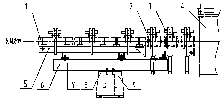
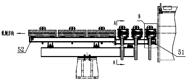
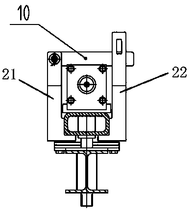
[0026] Such as Figure 1 to Figure 4 As shown, the water-piercing cooling air seal device of the present invention is located close to the back of the water-piercing cooling water cooling box 4, and includes a composite water beam 5, a beam 6, a base 9 and an air seal nozzle assembly 2, and the beam 6 is installed on the base 9, a composite water beam 5 is installed on the beam 6, the front end of the composite water beam 5 is provided with a circulating water inlet 51, and the rear end is provided with a circulating water outlet 52, and the composite water beam 5 is cooled by circulating water to prevent thermal deformation. The rear end of the beam 5 is equipped with a water-through cooling dry running tank 1, and the front end is equipped with a number of air seal nozzle assemblies 2. The compressed air inlet 15 connected to the intake pipe, and the position of the composite...


PUM


Abstract

The invention discloses a water penetrating cooling gas seal device, and belongs to the technical field of cooling equipment. The device comprises a composite water beam, a cross beam, a base and a gas seal nozzle assembly, the cross beam is mounted on the base, the cross beam is provided with the composite water beam, the rear end of the composite water beam is provided with a water penetrating cooling dry running through, the front end of the composite water beam is provided with multiple gas seal nozzle assemblies, the seal device is simple in structure and short in construction time, long-time production interruption cannot be caused, under the condition that a water cooling tank is not replaced, and through air spraying of gas seal nozzles, the phenomena that due to increasing of finished product speed, in order to ensure steel properties, the water pressure of the water cooling tank is increased, a large amount of cooling water is brought out by rolled metal and left in the dry run groove, remaining water in the dry run groove enables the rolled metal to be obstructed, steel stacking is caused, due to the fact that a naturally-cooled pinch roller has water, the water is brought in, a high-speed rotation high-temperature roller ring is cooled and exploded, and serious process and equipment accidents are caused can be avoided.

Description

technical field [0001] The invention relates to a water-piercing cooling air seal device, which belongs to the technical field of cooling equipment. Background technique [0002] The water cooling device is an indispensable equipment for high-speed wire rod production. Its function is to cool and control the temperature of the finished rolled wire rod. . The current slow cooling section mainly includes a water cooling box and a water beam equipped with a dry running tank. The back end of the water cooling box is equipped with a compressed air sealing device, which can effectively seal the water in the water cooling box and prevent the cooling water from being carried out by the rolled material and left behind. In the dry running trough, the rolled material transported from the water cooling box is cooled by the water beam and then sent to the laying machine through the pinch roller ring. [0003] With the continuous upgrading of rolling mills and the maturity of rolling te...

Claims


Application Information

Patent Timeline
Patent Type & Authority Applications(China)
IPC IPC(8): B21B45/02B21B45/00F26B21/00F26B21/12
CPCB21B45/0203B21B45/00F26B21/004F26B21/12
Inventor 陈静刘高明王建永
Owner XINXING DUCTILE IRON PIPES CO LTD
Learn More