Quantum dot light-emitting diode and preparation method thereof
A quantum dot light-emitting and diode technology, which is applied in semiconductor/solid-state device manufacturing, electrical components, circuits, etc., can solve the problems of short working life of quantum dot light-emitting diodes
- Summary
- Abstract
- Description
- Claims
- Application Information
AI Technical Summary
Problems solved by technology
Method used
Image
Examples
preparation example Construction
[0052] Such as Figure 5 As shown, some embodiments of the present invention provide a method for preparing a quantum dot light-emitting diode, comprising the following steps:
[0053] S01. Provide an anode substrate, the surface of the anode substrate is provided with an initial first metal oxide nanoparticle layer, and the first metal oxide nanoparticles in the initial first metal oxide nanoparticle layer are electron transport materials;
[0054] S02. Evaporating an initial second metal layer on the initial first metal oxide nanoparticle layer, and performing heat annealing treatment on the anode substrate on which the initial second metal layer is evaporated.
[0055] In some embodiments of the present invention, the anode substrate may include a substrate, an anode stacked on the surface of the substrate, and a quantum dot light-emitting layer stacked on the surface of the anode; in still other embodiments of the present invention, the anode substrate It may include a su...
Embodiment 1
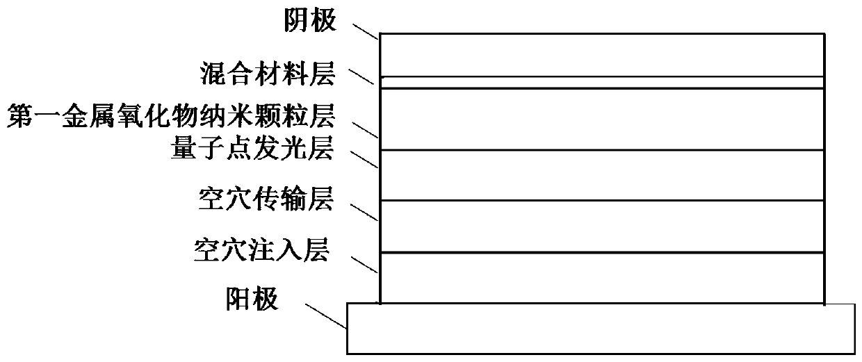
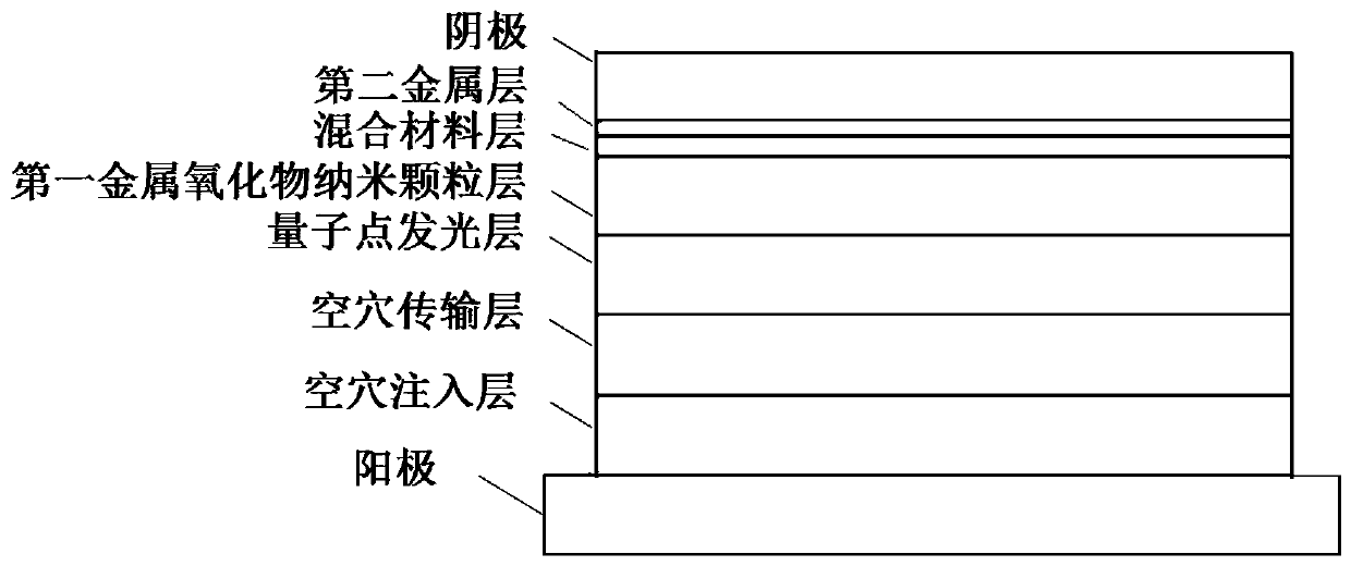
[0081] A method for preparing a positive top-emitting quantum dot light-emitting diode, comprising the following steps:
[0082] On the ITO substrate, spin-coat PEDOT:PSS, spin-coat at a speed of 5000rmp for 30 seconds, and then heat at a temperature of 150°C for 15 minutes to prepare a hole injection layer;
[0083] Spin-coat TFB on the hole injection layer at a speed of 8 mg / mL, spin-coat at a speed of 3000 rpm for 30 seconds, and then heat at a temperature of 150° C. for 30 minutes to prepare a hole-transport layer;
[0084] Spin-coat quantum dots on the hole transport layer at a speed of 20 mg / mL, and spin-coat for 30 seconds at a speed of 2000 rpm to prepare a quantum dot light-emitting layer;
[0085] Spin-coat nano-ZnO on the quantum dot light-emitting layer at a speed of 30 mg / mL, spin-coat for 30 seconds at a speed of 3000 rpm, and then heat for 30 minutes at a temperature of 80 ° C to prepare a nano-ZnO layer;
[0086] The vacuum degree is not higher than 3×10 -4 U...
Embodiment 2
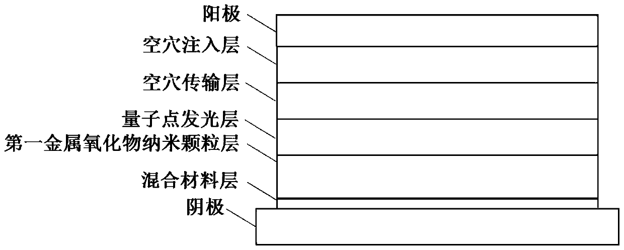
[0090] A method for preparing an inverted bottom-emitting quantum dot light-emitting diode, comprising the following steps:
[0091] On the ITO substrate, the vacuum degree is not higher than 3×10 -4 Evaporate Ag under the condition of Pa, the speed is 1 Angstrom / second, the time is 100 seconds, and the preparation thickness is the silver layer of 10nm;
[0092] Spin-coat nano-ZnO on the silver layer at a speed of 30 mg / mL at a speed of 3000, spin-coat for 30 seconds at a speed of 3000 rpm, and then heat at a temperature of 80 ° C for 30 minutes to prepare a nano-ZnO layer;
[0093] Place the sample on a heating plate pre-set to 120°C for 30 minutes to prepare the laminate;
[0094] Spin-coat quantum dots on the laminate at a speed of 20 mg / mL, and spin-coat for 30 seconds at a speed of 2000 rpm to prepare a quantum dot light-emitting layer;
[0095] Spin-coat PVK on the quantum dot light-emitting layer at a speed of 8 mg / mL, spin-coat for 30 seconds at a speed of 3000 rpm, ...
PUM
| Property | Measurement | Unit |
|---|---|---|
| thickness | aaaaa | aaaaa |
| thickness | aaaaa | aaaaa |
| thickness | aaaaa | aaaaa |
Abstract
Description
Claims
Application Information
 - R&D
- Intellectual Property
- Life Sciences
- Materials
- Tech Scout
- Unparalleled Data Quality
- Higher Quality Content
- 60% Fewer Hallucinations
Browse by: Latest US Patents, China's latest patents, Technical Efficacy Thesaurus, Application Domain, Technology Topic, Popular Technical Reports.
© 2025 PatSnap. All rights reserved.Legal|Privacy policy|Modern Slavery Act Transparency Statement|Sitemap|About US| Contact US: help@patsnap.com


