
Preparation method of heterogeneous bonding structure

A heterogeneous bonding and bonding technology, applied in semiconductor/solid-state device manufacturing, electrical components, circuits, etc., can solve the problems of large wafer thickness, affecting the lithography accuracy of device structure, and inability to apply

Active Publication Date: 2020-07-07
上海新硅聚合半导体有限公司
View PDF6 Cites 4 Cited by
  • Summary
  • Abstract
  • Description
  • Claims
  • Application Information

AI Technical Summary

Problems solved by technology

However, due to the large thickness of the wafer used for wafer bonding (generally greater than 200 microns) and the mismatch of thermal expansion coefficients between the heterogeneous materials, the pre-bonded heterogeneous bonded structure will be relatively weak during high temperature annealing. Large thermal stress leads to deformation of the bonding structure
After the bonded structure is cooled to room temperature, the thermal stress generated by post-high temperature annealing cannot be completely released, so there is residual thermal stress inside the heterogeneous bonded structure, resulting in a large warpage of the bonded structure after cooling to room temperature
Since the current wafer processing uses vacuum adsorption or electrostatic adsorption to fix the wafer, the wafer warpage is too large to be adsorbed, so it cannot continue to be used in the subsequent processing technology.
In addition, with the shrinking of micro-nano processing lines in semiconductor technology, large wafer warpage will seriously affect the lithography accuracy of the device structure, thereby reducing the yield of device fabrication and device performance

Method used


Image

  • Preparation method of heterogeneous bonding structure
  • Preparation method of heterogeneous bonding structure
  • Preparation method of heterogeneous bonding structure

Examples


Embodiment Construction

[0042] Embodiments of the present invention are described below through specific examples, and those skilled in the art can easily understand other advantages and effects of the present invention from the content disclosed in this specification. The present invention can also be implemented or applied through other different specific implementation modes, and various modifications or changes can be made to the details in this specification based on different viewpoints and applications without departing from the spirit of the present invention.

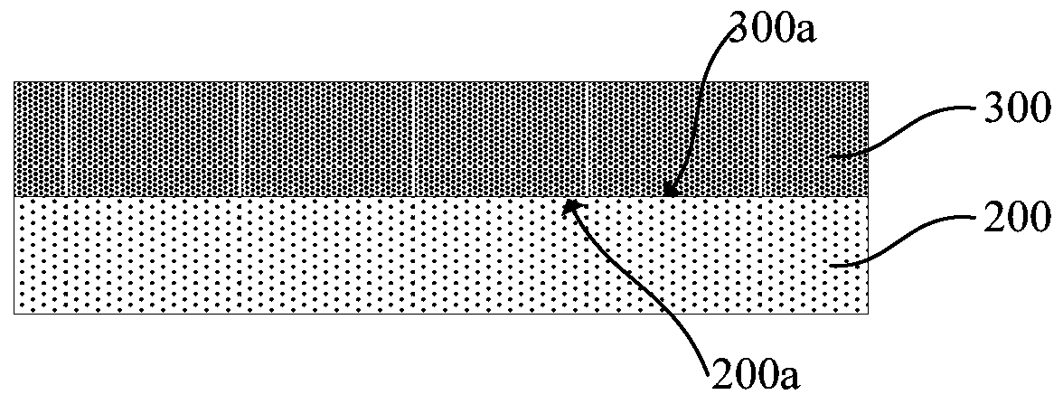
[0043] see Figure 2 to Figure 6 . It should be noted that the diagrams provided in this embodiment are only schematically illustrating the basic concept of the present invention, although only the components related to the present invention are shown in the diagrams rather than the number, shape and Dimensional drawing, the shape, quantity and proportion of each component can be changed arbitrarily during actual implementation, and ...


PUM


Abstract

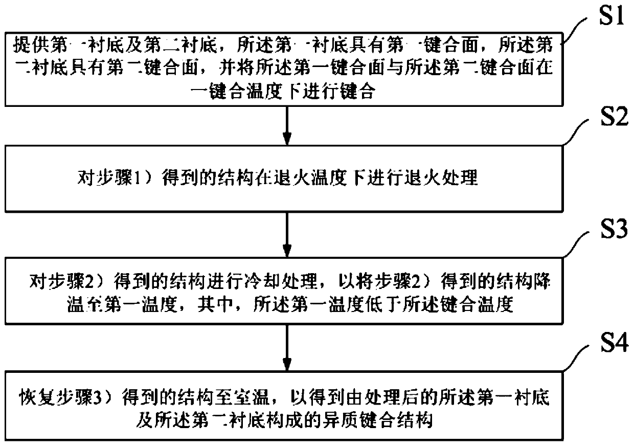
The invention provides a preparation method of a heterogeneous bonding structure, which comprises the steps of providing a first substrate and a second substrate, wherein the first substrate is provided with a first bonding surface, the second substrate is provided with a second bonding surface, and the first bonding surface and the second bonding surface are subjected to bonding treatment at a bonding temperature; conducting annealing treatment at an annealing treatment temperature; carrying out cooling treatment to reduce the temperature to a first temperature which is lower than the bondingtemperature; and adjusting the temperature of the structure obtained in the previous step to room temperature so as to obtain a heterogeneous bonding structure formed by the treated first substrate and second substrate. According to the preparation method of the heterogeneous bonding structure, the reinforced structure is cooled to a temperature below the bonding temperature after annealing treatment reinforcement, so that thermal stress opposite to that in the heating process is generated in the cooling treatment process, residual thermal stress in the heterogeneous bonding structure is reduced, and warping of the bonding structure caused by stress can be reduced.

Description

technical field [0001] The invention belongs to the technical field of substrate preparation, in particular to a method for preparing a heterogeneous bonding structure. Background technique [0002] With the development of electronic information technology, devices with a single function have been unable to meet people's needs for device miniaturization and functional diversification. Therefore, the heterogeneous integration of materials or devices with different functions to develop multifunctional integrated electronic modules has become the development direction of electronic technology. For example, NGAS in the United States uses heterogeneous integration technology to integrate InP devices, GaN devices and Si-CMOS devices. Raytheon Corporation of the United States uses heteroepitaxy technology to integrate InP devices with silicon devices. [0003] At present, there are mainly two solutions for heterogeneous integration of different functional materials: heteroepitaxy...

Claims


Application Information

Patent Timeline
IPC IPC(8): H01L21/18H01L21/02
CPCH01L21/02H01L21/187
Inventor 欧欣黄凯李文琴赵晓蒙鄢有泉李忠旭王曦
Owner 上海新硅聚合半导体有限公司
Learn More