
Grounding connection structure of gas spray header in plasma processing device

A gas shower head and plasma technology, applied in the field of plasma treatment, can solve problems such as unstable conduction effect, shortened service life of bolts, uneven distribution of plasma, etc.

Active Publication Date: 2020-07-07
ADVANCED MICRO FAB EQUIP INC CHINA
View PDF11 Cites 0 Cited by
  • Summary
  • Abstract
  • Description
  • Claims
  • Application Information

AI Technical Summary

Problems solved by technology

However, the bolt, such as the position of the thread, is prone to arcing, and oxides (such as iron oxide) will accumulate on the surface, thereby increasing the resistance of the bolt and making its conductive effect in the grounding path unstable. And make the radio frequency circuit have high impedance, thus consume a lot of radio frequency energy and reduce the conduction efficiency
[0006]Bolts also bear heat from the mounting base and the sprinkler head, and have a different coefficient of thermal expansion from the components they are connected to Looseness or slippage at the connection interface between the seat and the gas shower head, causing the ground path of the RF loop to deviate
These will shorten the service life of the bolts, destroy the uniform distribution of the electric field in the reaction chamber, and cause the condition of radio frequency discharge to shift, resulting in uneven distribution of plasma in the reaction chamber, thus affecting the uniformity of substrate processing

Method used


Image

  • Grounding connection structure of gas spray header in plasma processing device
  • Grounding connection structure of gas spray header in plasma processing device
  • Grounding connection structure of gas spray header in plasma processing device

Examples


Embodiment Construction

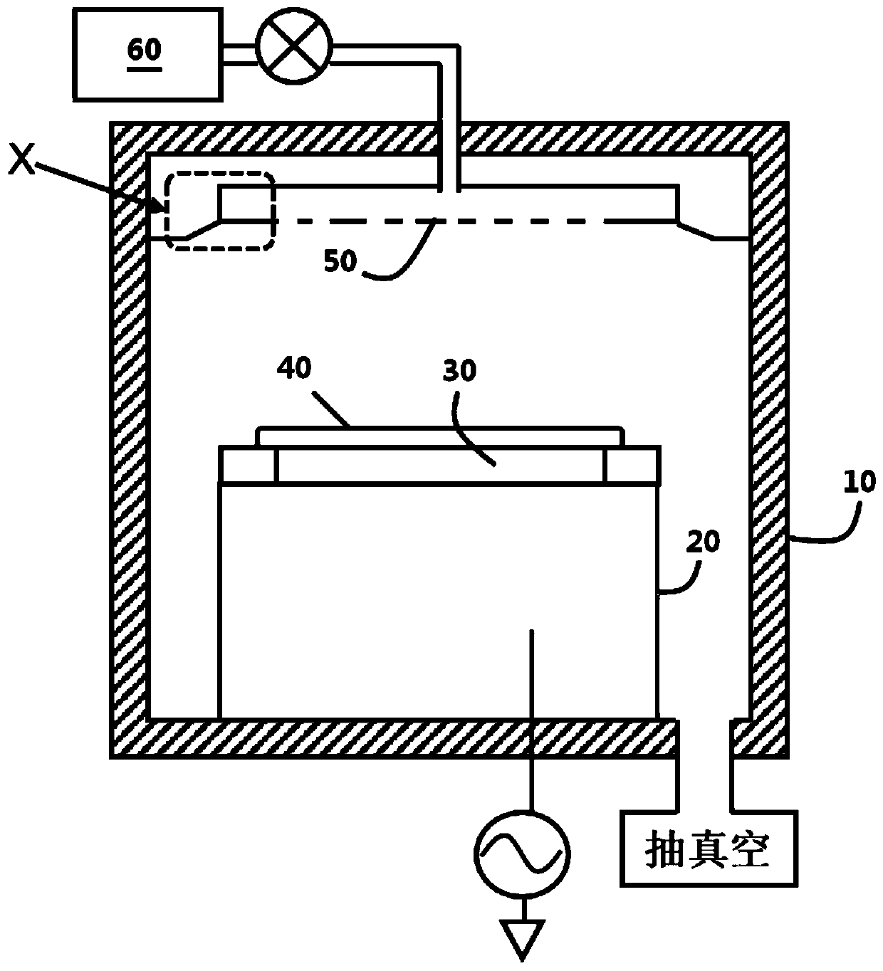
[0034] figure 1 Shown is a capacitively coupled plasma processing device, including a vacuumable reaction chamber 10, a substrate support base 20 is arranged below the reaction chamber 10, and the substrate is fixed by an electrostatic chuck 30 on the substrate support base 20 40. The substrate support base 20 is usually applied with at least one radio frequency power source as the lower electrode, and by coupling the radio frequency power into the reaction chamber 10, the gas delivered by the gas supply device 60 into the reaction chamber 10 is dissociated into plasma, The processing of the substrate 40 is realized.

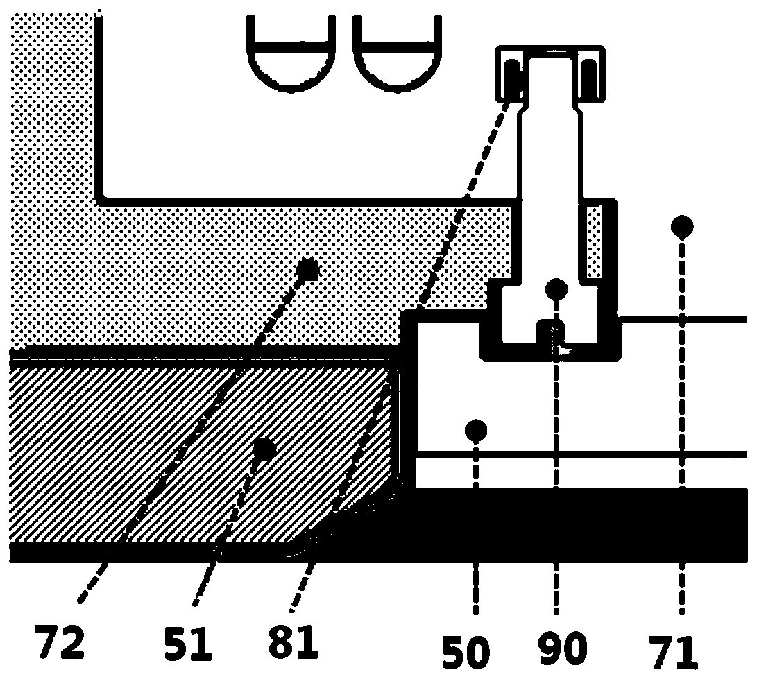
[0035]The reaction gas output by the gas supply device 60 is evenly transported into the reaction chamber 10 through the vent holes distributed on a gas shower head 50; RF power signal coupled to the upper electrode. In order to form a radio frequency current loop, the gas shower head 50 is usually connected to a grounded mounting base on the top of the reacti...


PUM


Abstract

The invention relates to a grounding connection structure of a gas spray header in a plasma processing device, which is characterized in that the gas spray header, a mounting base and a base plate between the gas spray header and the mounting base are tightly matched through a connecting fastener; the mounting hole of the mounting base is provided with a conductive part and an elastic element; theconductive part forms an internal space and is used for accommodating the front end of the connecting fastener inserted into the mounting hole; the elastic force of the elastic element acts on the conductive part, so that the conductive part is in close contact with the mounting base, and the conductive part is in close contact with the connecting fastener. The structure has an anti-loosening mechanism, so that devices can be fixedly installed, and deviation generated near the connecting fastener in the using process is corrected. When the connecting fastener is used for conducting current, tight contact between the conductive part and the connecting fastener as well as between the conductive part and the mounting base can be effectively ensured, and the stability and reliability of a current transmission path are ensured.

Description

technical field [0001] The invention relates to the field of plasma processing, in particular to a ground connection structure of a gas shower head in a plasma processing device. Background technique [0002] An existing capacitively coupled plasma processing device includes a vacuumable reaction chamber, a gas shower head that uniformly injects reaction gas into the reaction chamber, and is usually used as an upper electrode to connect with a grounded installation base on the top of the reaction chamber The substrate supporting device opposite to the gas shower head is usually used as the lower electrode and connected to at least one radio frequency power source, an electric field is established between the upper and lower electrodes, and the reaction gas introduced into the reaction chamber is dissociated to form plasma. RF power is coupled to the gas showerhead and then conducted to the mounting base, forming a ground path for the RF current. Under high-power process con...

Claims


Application Information

Patent Timeline
Patent Type & Authority Applications(China)
IPC IPC(8): H01J37/32
CPCH01J37/32431H01J37/32798H01J37/32908
Inventor 麦仕义廉晓芳魏强张辉
Owner ADVANCED MICRO FAB EQUIP INC CHINA
Learn More