
Guide Rail Having Base Rail And Gear Rack, Method Of Making Same, Guide Assembly Including Same

a technology of guide rails and gear racks, applied in the direction of manufacturing tools, mechanical devices, metal working devices, etc., to achieve the effect of increasing accuracy

Inactive Publication Date: 2010-05-27
PACIFIC BEARING
View PDF26 Cites 46 Cited by
  • Summary
  • Abstract
  • Description
  • Claims
  • Application Information

AI Technical Summary

Benefits of technology

The present invention relates to guide rails with gear racks that are precision located relative to the raceways of the guide rail. The guide rail has a base rail with a gear rack and a raceway. The gear rack is mounted to the base rail and interacts with a pinion on a cooperating carriage or frame member. The guide rail has a high degree of parallelism between the gear rack and the reference point on the guide rail, which ensures a precise mesh between the pinion gear and the gear rack, even if there are slight bows or variations in the guide rail. The guide rail is formed with a hardened rail or a machined reference point on the base rail. The guide assembly includes a pinion and guide rollers or similar structures for interacting with the raceways of the guide rail. The technical effects of the invention include improved accuracy and stability of the guide rail and reduced vibration and biasing of the gear rack.

Problems solved by technology

This arrangement also prevents additional areas for tolerance loss due to tightening of a threaded connector that can result in undesirable biasing of the gear rack relative to the base rail.

Method used


Image

  • Guide Rail Having Base Rail And Gear Rack, Method Of Making Same, Guide Assembly Including Same
  • Guide Rail Having Base Rail And Gear Rack, Method Of Making Same, Guide Assembly Including Same
  • Guide Rail Having Base Rail And Gear Rack, Method Of Making Same, Guide Assembly Including Same

Examples


Embodiment Construction

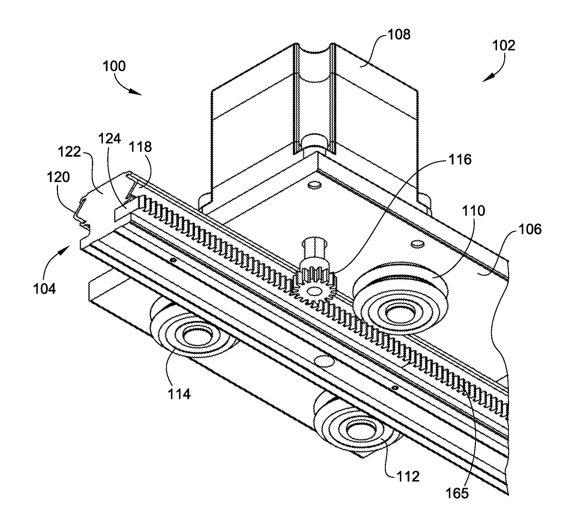
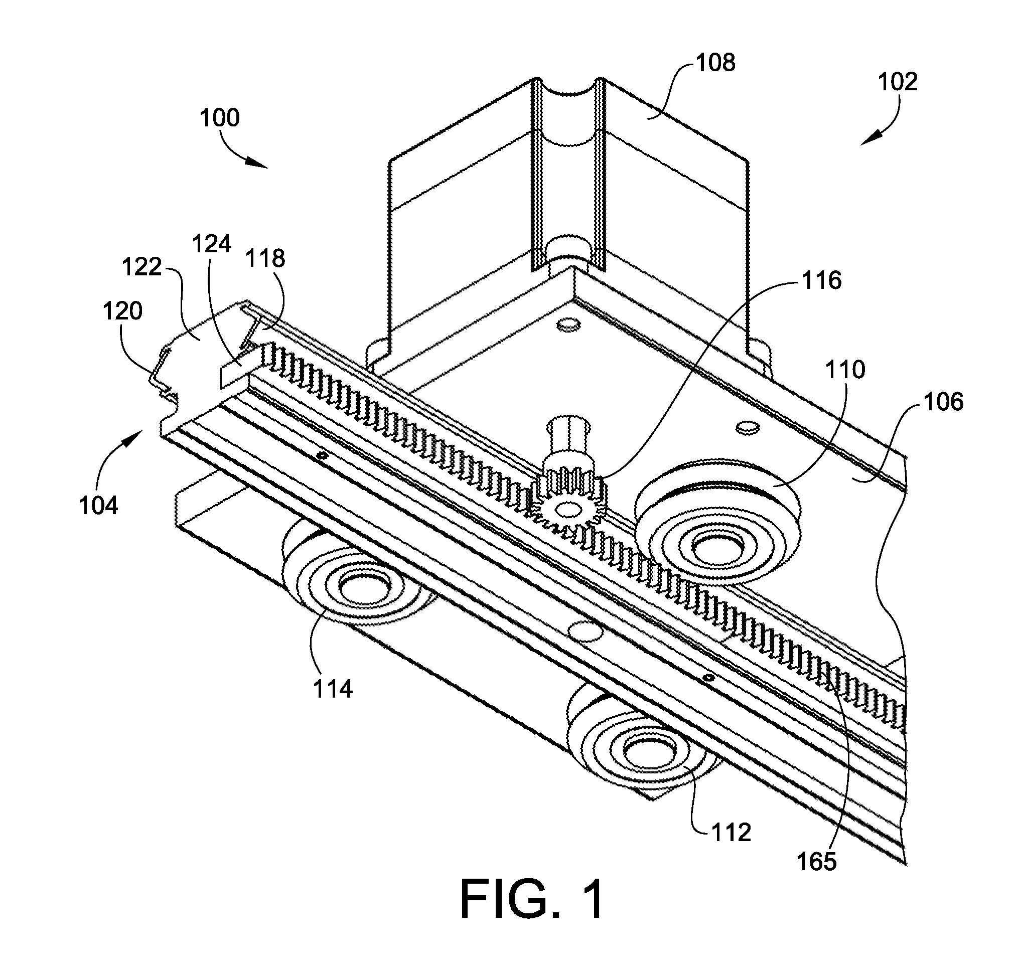
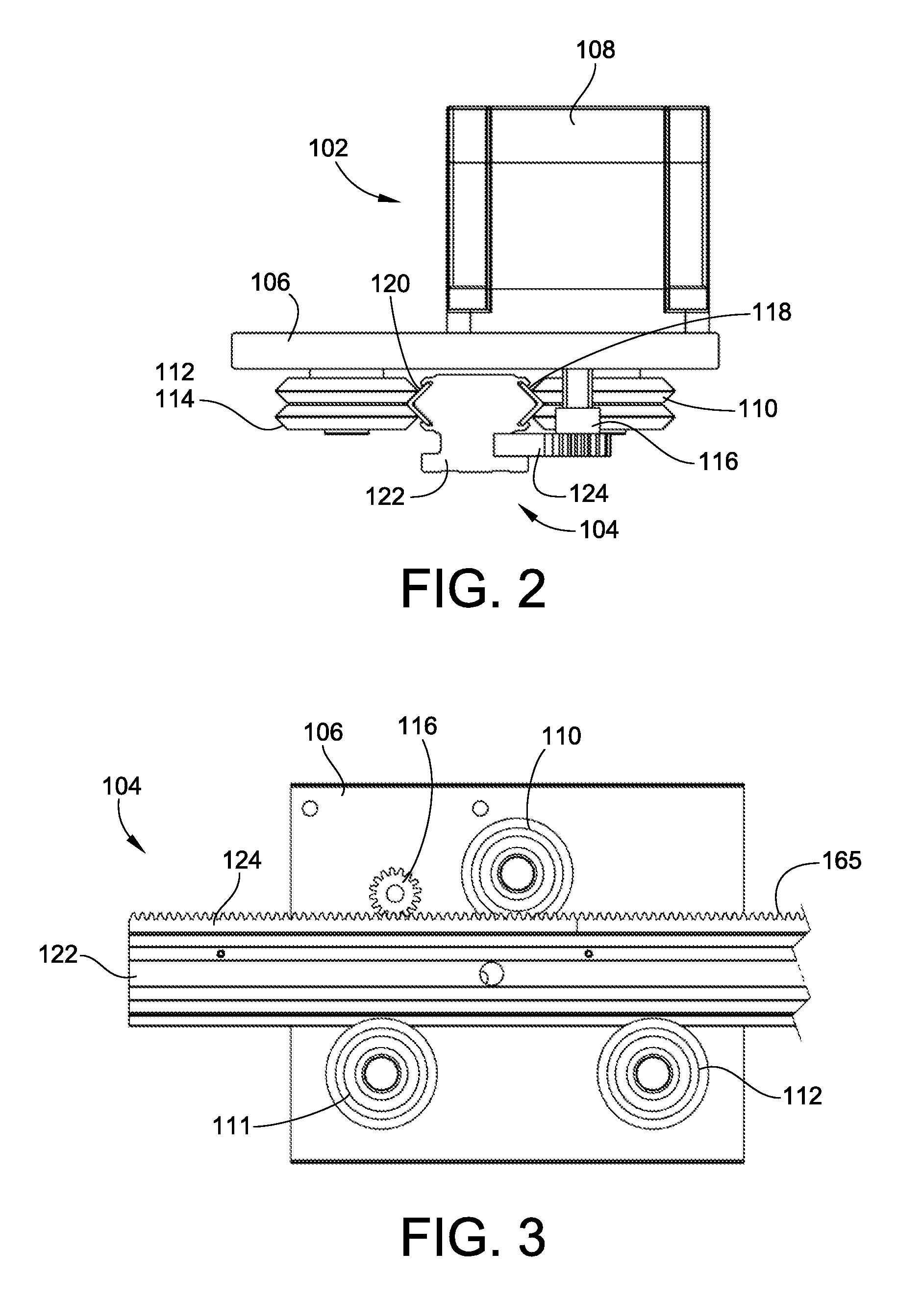
[0030]FIGS. 1-4 illustrate an embodiment of a guide assembly 100 that includes a carriage assembly 102 and a linear guide rail 104. The carriage assembly 102 and linear guide rail 104 are coupled for relative motion. Therefore, the carriage assembly 102 can be driven along the linear guide rail 104 to position devices attached to the carriage assembly 102 relative to the linear guide rail 104. Alternatively, the carriage assembly 102 could be in the form of a fixed position frame member that is in fact a stationary component relative to which the linear guide rail 104 moves. In this alternative arrangement, the linear guide rail 104 would be attached to a device to move the attached device relative to the carriage assembly 102.

[0031]The carriage assembly 102 generally includes a base member 106, a motor 108 and a plurality of guide rollers 110, 112, 114. The motor 108 and guide rollers 110, 112, 114 are operably mounted to the base member and are generally carried thereby. The motor...


PUM

PropertyMeasurementUnit
pitch diameteraaaaaaaaaa
lengthaaaaaaaaaa
pitch diameteraaaaaaaaaa

Abstract

A guide rail is provided. The guide rail includes a base rail and a gear rack mounted to the base rail. The guide rail also provides at least one race upon which a guide roller can ride. The guide rail defines a reference point related to the raceway that has a parallelism relative to the gear rack of less than or equal to 0.005 inches per foot along the length of the guide rail. Preferably, the reference point is defined directly by the raceway and the parallelism is less than or equal to 0.001 inches per foot. A method of forming the guide rail is also provided. The method includes machining the reference point into the guide rail and using the reference point to locate machining a seat for mounting the gear rack. A guide assembly including a guide rail and a carriage or frame structure is also provided.

Description

CROSS-REFERENCE TO RELATED PATENT APPLICATIONS[0001]This patent application claims the benefit of U.S. Provisional Patent Application No. 61 / 117,795, filed Nov. 25, 2008, the disclosure and teachings of which are incorporated herein, in their entireties, by reference thereto.FIELD OF THE INVENTION[0002]This invention generally relates to guide assemblies and more particularly to guide rails for linear motion.BACKGROUND OF THE INVENTION[0003]Guide assemblies have been used for assisting in guided linear motion of many products including medical scanners, printer devices, machining devices and automatic door openers, such as for elevators.[0004]Typically, a guide assembly will include a guide rail and a carriage or frame. The carriage or frame and the guide rail move relative to one another for coordinated linear motion. Typically, the carriage or frame will include at least one guide roller or similar rolling element that interacts with and rides on a raceway of the guide rail to pro...

Claims


Application Information

Patent Timeline
Patent Type & Authority Applications(United States)
IPC IPC(8): F16C29/06B23P11/00
CPCF16C29/045Y10T29/49826F16C29/005
Inventor SCHROEDER, JONATHAN R.LECRONE, TIMOTHY J.BINKA, JOSEPH A.
Owner PACIFIC BEARING
Learn More