An ion trap system
An ion trap and ion technology, applied in the field of ion trap systems, can solve the problems of beam and ion dislocation, change of beam transmission direction, affecting the fidelity of quantum state manipulation, etc.
- Summary
- Abstract
- Description
- Claims
- Application Information
AI Technical Summary
Problems solved by technology
Method used
Image
Examples
example 1
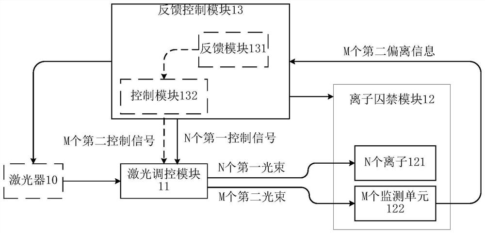
[0147] Figure 4A Another ion trap system architecture provided in the present application. like Figure 4A As shown, the ion trap system includes a laser regulating module 11, an ion prisoner module 12, a feedback module 131, and a control module 132. The laser regulating module 11 includes a first beam member 111a, a lens 112a, n first MEMS mirror 113a, a m second MEMS mirror 114a and an objective lens 115a, n first beam and N first MEMS mirror 113a One correspondence, the M second beam corresponds to one one one one by one, i.e., a first MEMS mirror 113a, can change a first beam with the transmission direction, and a second MEMS mirror 114a can change. A second beam transport direction.
[0148] The first beam unit 111a is used to divide the beam from the laser into N first beams and M second beams. In a possible implementation, the first beam unit 111a can also be used to divide the beam from the laser into P first beam and the second beam, where N first beam belongs to P first...
example 2
[0187] like Figure 4B Shown, a schematic view of still another ion trap of the present application provides a system configuration. The ion trap includes a laser-control system module 11, the ion trapping module 12, the feedback module 131 and control module 132. Regulatory module 11 includes a first laser beam splitter 111a, a lens 112a, N of first micro-electromechanical system MEMS mirror 113a, M second MEMS mirror 114a, 115a and the objective lens AOM116a, the control module 132 includes an RF source 1321. AOM116a comprising N first channels and M second channels (e.g. Figure 4B FIG filled with different patterns identified), N first channels correspond to the N first beam, M second channels correspond to M second light beam, and the first channel and the N-th M there is no overlap between the two channels, the first channel and the N second channels and M are independently regulated.
[0188] AOM116a, for the first beam splitter through the lenses 111a and 112a of the N first...
example 3
[0205] like Figure 4D As shown, it is a schematic diagram of still another ion trap system for the present application. The ion trap system can be in the above Figure 4B The first switch 1322a and the second switch 1323a are added to the control module 132 in the ion trap system shown. The first switch 1322a is configured to control the N first passages of the AOM116A, and the second switch 1323a is used to control the M second channels of the AOM 116A, and the n first channels and M second channels can be independently regulated separately. The first switch 1322a is configured to control the state of the first switch according to the seventh control signal of the control module 132, and the seventh control signal is determined by the timing dimension according to the timing of the quantum state control of the N ion 121. The appearance is constantly switching. The second switch 1323a is configured to control the second switch to keep the open state according to the eighth control ...
PUM
 Abstract
Description
Claims
Application Information
 - R&D
- Intellectual Property
- Life Sciences
- Materials
- Tech Scout
- Unparalleled Data Quality
- Higher Quality Content
- 60% Fewer Hallucinations
Browse by: Latest US Patents, China's latest patents, Technical Efficacy Thesaurus, Application Domain, Technology Topic, Popular Technical Reports.
© 2025 PatSnap. All rights reserved.Legal|Privacy policy|Modern Slavery Act Transparency Statement|Sitemap|About US| Contact US: help@patsnap.com


