Ion trap system
An ion trap and ion technology, applied in the field of ion trap systems, can solve problems such as misalignment of beams and ions, changes in beam transmission directions, and inability to align beams with ions
- Summary
- Abstract
- Description
- Claims
- Application Information
AI Technical Summary
Problems solved by technology
Method used
Image
Examples
example 1
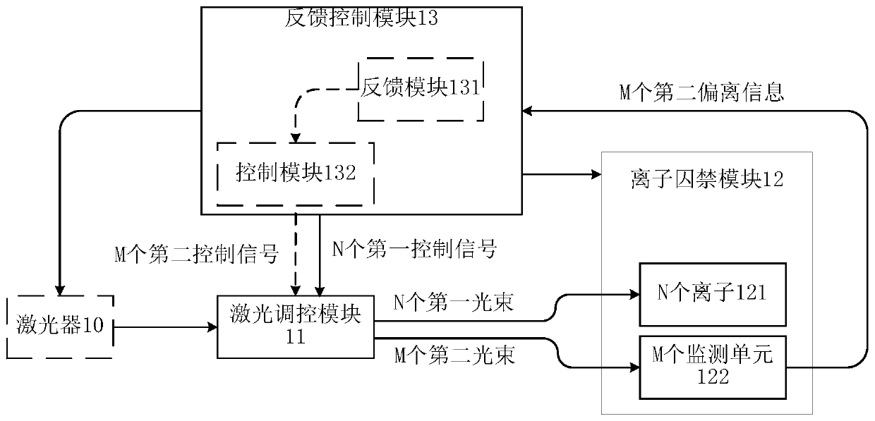
[0147] Figure 4a It is a schematic diagram of another ion trap system architecture provided in this application. Such as Figure 4a As shown, the ion trap system includes a laser regulation module 11 , an ion trapping module 12 , a feedback module 131 and a control module 132 . The laser control module 11 includes a first beam splitter 111a, a lens 112a, N first MEMS mirrors 113a, M second MEMS mirrors 114a and an objective lens 115a, N first light beams and N first MEMS mirrors 113a One-to-one correspondence, M second beams correspond to M second MEMS mirrors 114a one-to-one, that is, a first MEMS mirror 113a can change the transmission direction of a first beam and a second MEMS mirror 114a can change A direction of propagation of the second light beam.
[0148] The first beam splitter 111a is used for splitting the beam from the laser into N first beams and M second beams. In a possible implementation manner, the first beam splitter 111a can also be used to divide the ...
example 2
[0187] Such as Figure 4b As shown, it is a schematic structural diagram of another ion trap system provided by the present application. The ion trap system includes a laser regulation module 11 , an ion trapping module 12 , a feedback module 131 and a control module 132 . The laser control module 11 includes a first beam splitter 111a, a lens 112a, N first MEMS mirrors 113a, M second MEMS mirrors 114a, an objective lens 115a and an AOM 116a, and the control module 132 includes an RF source 1321. AOM116a includes N first channels and M second channels (such as Figure 4b shown with filling marks of different patterns), N first channels are in one-to-one correspondence with N first beams, M second channels are in one-to-one correspondence with M second beams, and N first channels and M first beams are in one-to-one correspondence There is no overlap between the two channels, and the N first channels and the M second channels are independently regulated.
[0188] AOM116a, for...
example 3
[0205] Such as Figure 4d As shown, it is a schematic diagram of another ion trap system architecture provided by the present application. The ion trap system can be used in the above Figure 4b A first switch 1322a and a second switch 1323a are added to the control module 132 in the ion trap system shown. The first switch 1322a is used to control the N first channels of the AOM 116a, the second switch 1323a is used to control the M second channels of the AOM 116a, and the N first channels and the M second channels can be controlled independently. The first switch 1322a is used to control the state of the first switch according to the seventh control signal of the control module 132. The seventh control signal is determined by the control module 132 according to the timing of the manipulation of the quantum states of the N ions 121, in the time dimension The above performance is constantly switching. The second switch 1323a is used to control the second switch to remain ope...
PUM
 Abstract
Description
Claims
Application Information
 - R&D
- Intellectual Property
- Life Sciences
- Materials
- Tech Scout
- Unparalleled Data Quality
- Higher Quality Content
- 60% Fewer Hallucinations
Browse by: Latest US Patents, China's latest patents, Technical Efficacy Thesaurus, Application Domain, Technology Topic, Popular Technical Reports.
© 2025 PatSnap. All rights reserved.Legal|Privacy policy|Modern Slavery Act Transparency Statement|Sitemap|About US| Contact US: help@patsnap.com


