
Ground pre-grouting method for small-section high shaft in complex stratum

A complex formation, pre-grouting technology, applied in well sinking, shaft equipment, earth-moving drilling, etc., can solve the problems of difficult seating, risk of water production, and easy to return to the wellbore, so as to reduce the waste of slurry and reduce the difficulty. , Guarantee the effect of grouting quality

Active Publication Date: 2020-07-03
BEIJING CHINA COAL MINE ENG CO LTD
View PDF10 Cites 4 Cited by
  • Summary
  • Abstract
  • Description
  • Claims
  • Application Information

AI Technical Summary

Problems solved by technology

[0015] For this reason, the technical problem to be solved by the present invention is to provide a method for surface pre-grouting of small and high wellbore in complex formations, which solves the problem in the prior art that complex formations with broken and large section heights are not easy to be sealed during the grouting process. , Slurry return accidents are prone to occur after sealing, and there is a risk of water outflow during wellbore excavation after grouting

Method used


Image

  • Ground pre-grouting method for small-section high shaft in complex stratum
  • Ground pre-grouting method for small-section high shaft in complex stratum
  • Ground pre-grouting method for small-section high shaft in complex stratum

Examples


Embodiment Construction

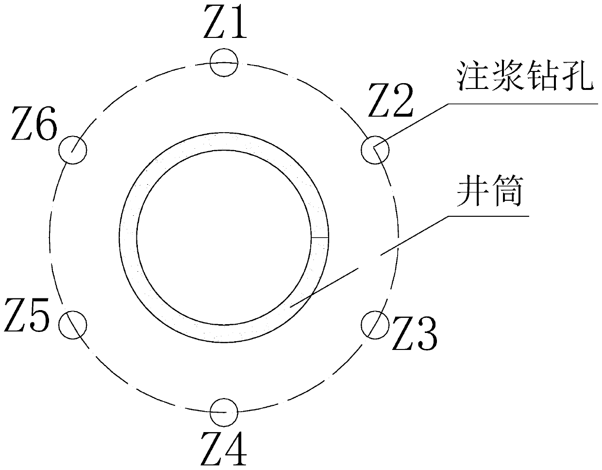
[0060] The ground pre-grouting method for small and high shafts in complex formations in this embodiment includes the following steps:

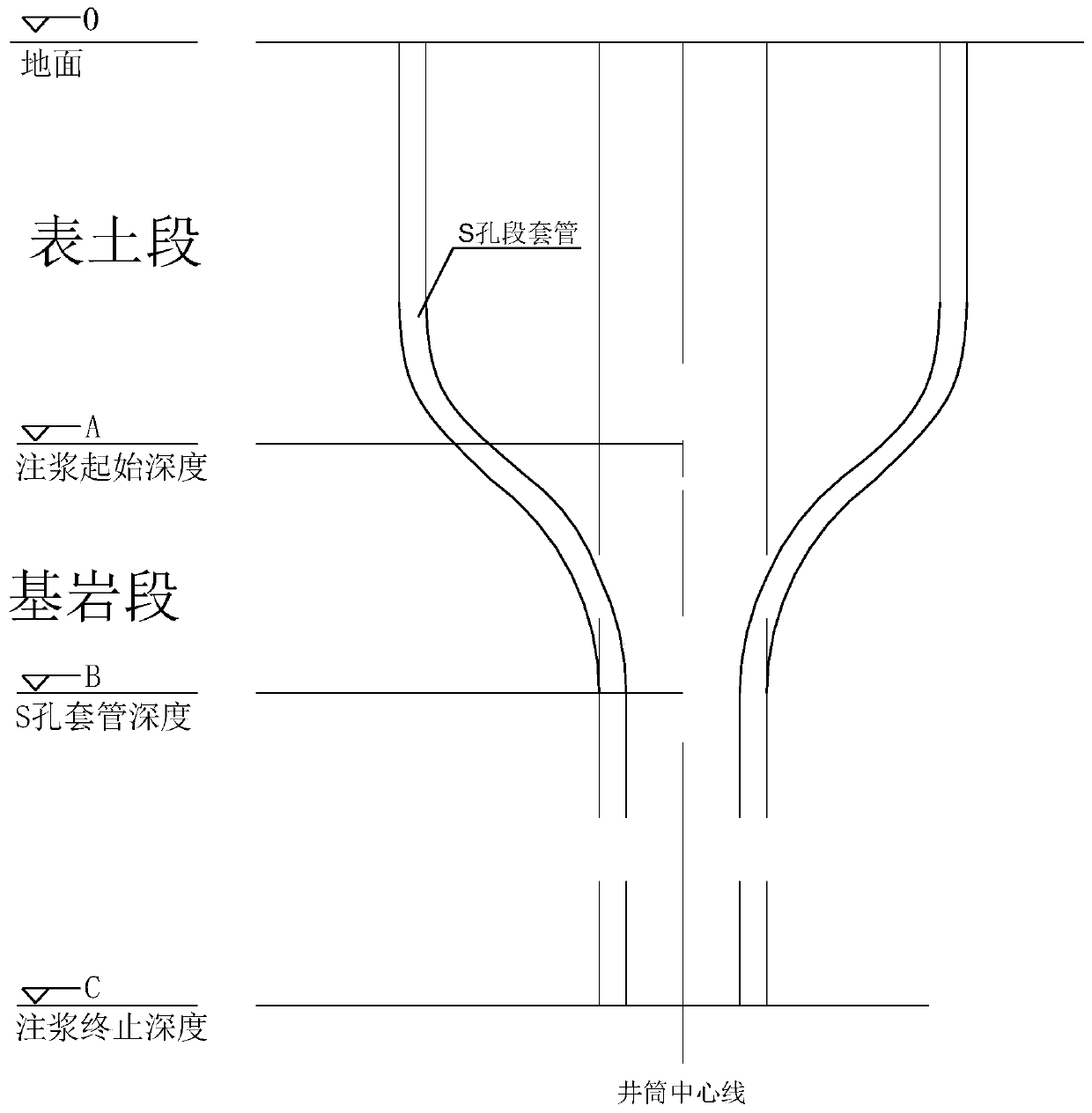
[0061] (1) Complete the grouting work of surface soil section solid pipe, AB section and CD section according to the method in the prior art, and complete the large section grouting operation of BC section, BC section is the complex stratum of broken zone; A is the grouting starting point B is the starting point of the broken zone, C is the ending point of the broken zone, and D is the ending point of grouting.

[0062] The topsoil section can adopt the full straight grouting drilling method or the S-type grouting drilling method.

[0063] This embodiment adopts the full straight grouting drilling method, A is the starting point of grouting, B is the starting point of the broken zone, C is the ending point of the broken zone, and D is the ending point of grouting. The height from the ground to the grouting starting point A is the surface soi...


PUM


Abstract

The invention discloses a ground pre-grouting method for a small-section high shaft in a complex stratum. The ground pre-grouting method comprises the steps that (1) according to the prior art, surface soil section pipe fixing and grouting work of an AB section and a CD section are completed, and large-section grouting work of a BC section is completed; (2) the grouted CD section below the groutedBC section is subjected to hole sealing through cement; (3) the BC section of a crushing belt undergoes pipe swinging; (4) the BC section of the crushing belt is subjected to pipe fixing; (5) small-section high perforation work is conducted on the BC section of the crushing belt; (6) grouting construction is conducted on a small-section high perforation section; (7) after the small-section high perforation section reaches the grouting ending standard, slip type grouting-stopping plugs are adopted for stopping grouting; and (8) small-section high perforation work and grouting construction arecontinuously conducted on the previous section of the small-section high perforation section of the BC section of the crushing belt, and the steps (5)-(7) are repeated till perforation and grouting work of the BC section of the crushing belt are completed. The perforation grouting process can achieve precise sectioning and small-section high grouting, and thus the ground pre-grouting technology issuitable for more geological conditions.

Description

technical field [0001] The invention relates to the technical field of drilling exploration. Specifically, it is a method of pre-grouting on the surface of a small section of a high wellbore in a complex formation. Background technique [0002] Wellbore surface pre-grouting is to use a drilling rig to construct grouting holes around the wellbore from the ground before the wellbore is excavated, and use the grouting pump to send the prepared grout to the bedrock aquifer through the grouting pipeline and the grouting hole In the process, with the filling and solidification of the grout, an effective grouting curtain is formed around the wellbore to achieve the purpose of water blocking and formation reinforcement. In 1958, the ground pre-grouting technology was applied for the first time in the main and auxiliary shafts of Xuecun Coal Mine in Fengfeng mining area, and the water blocking rate reached 96.3%. Because the surface pre-grouting is carried out before the wellbore e...

Claims


Application Information

Patent Timeline
Patent Type & Authority Applications(China)
IPC IPC(8): E21D1/16E21B33/138
CPCE21B33/138E21D1/16
Inventor 陈振国梁敏刘书杰李生生贺文邓昀杨明高晓耕冯旭海杨雪陈君
Owner BEIJING CHINA COAL MINE ENG CO LTD
Learn More