Combined operation system of air source heat pump air conditioner and heat pump water heater

An air source heat pump and heat pump water heater technology, which is applied in air conditioning systems, heat pumps, fluid heaters, etc., can solve problems such as inefficient energy utilization, achieve optimized energy utilization efficiency, improve defrosting efficiency, and have strong system universality Effect

Active Publication Date: 2020-06-26
TONGJI UNIV
View PDF9 Cites 5 Cited by
  • Summary
  • Abstract
  • Description
  • Claims
  • Application Information

AI Technical Summary

Problems solved by technology

[0005] The purpose of the present invention is to provide a joint operation system of air source heat pump air conditioner and heat pump water heater in order to overcome the above-mentioned defects in the prior art, which solves the current situation that the energy utilization of heat pump systems in buildings is not efficient enough, and solves the problem of frosting from The design level of the overall system provides a complete solution

Method used


Image

  • Combined operation system of air source heat pump air conditioner and heat pump water heater
  • Combined operation system of air source heat pump air conditioner and heat pump water heater
  • Combined operation system of air source heat pump air conditioner and heat pump water heater

Examples


Embodiment 1

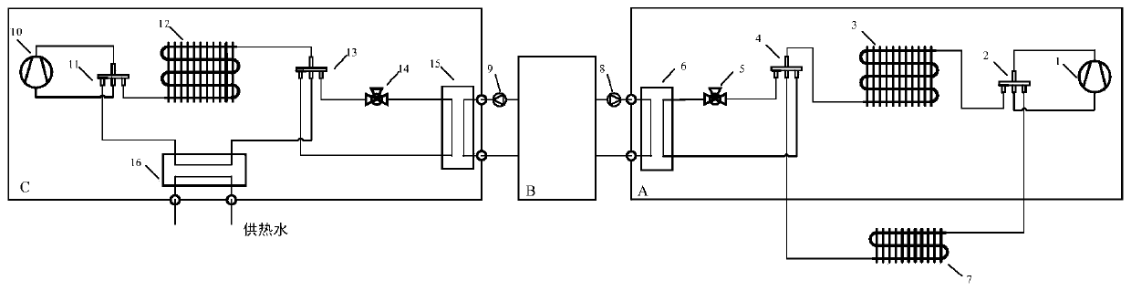
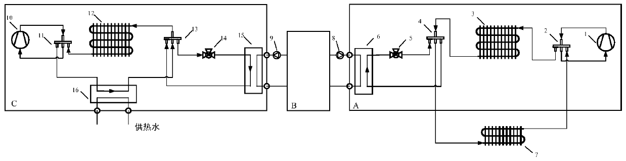
[0041] In this embodiment, the joint operation system of air source heat pump air conditioner and heat pump water heater, such as figure 1 shown, including:

[0042] Refrigerant circulation circuit: mainly includes the refrigerant circulation of the air source heat pump air conditioner mechanism and the refrigerant circulation of the air source heat pump water heater mechanism. The connection relationship of the components in the refrigerant cycle of the air source heat pump air conditioner is as follows: the first port, the second port, the third port, and the fourth port of the first four-way reversing valve 2 are respectively connected to the outlet port of the first compressor 1, The first outdoor coil 3, the inlet port of the first compressor 1, and the indoor coil 7 are connected through refrigerant pipes, and the first port, the second port, the third port, and the fourth port of the second four-way reversing valve 4 are respectively connected to the The first outdoor ...

Embodiment 2

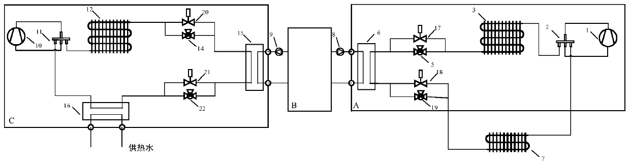
[0061] figure 2 Shown is another structural form of a combined operation system of an air source heat pump air conditioner and a heat pump water heater. its with figure 1 The difference is that the second four-way reversing valve 4 and the fourth four-way reversing valve 13 are replaced by the first two-way solenoid valve 17, the second two-way solenoid valve 18, the third throttling device 19 and the third two-way solenoid valve 20 , the fourth two-way solenoid valve 21 , and the fourth throttling device 22 .

[0062] The specific implementation form is: under summer working conditions, open the first two-way solenoid valve 17 (the third two-way solenoid valve 20), close the second two-way solenoid valve 18 (the fourth two-way solenoid valve 21); The second two-way solenoid valve 18 (the fourth two-way solenoid valve 21) closes the first two-way solenoid valve 17 (the third two-way solenoid valve 20).


PUM


Abstract

The invention relates to a combined operation system of an air source heat pump air conditioner and a heat pump water heater. The combined operation system comprises an air source heat pump air conditioning mechanism, a water storage tank mechanism and an air source heat pump water heater mechanism. The air source heat pump air conditioning mechanism and the water storage tank mechanism are connected in a heat exchange mode, and the water storage tank mechanism and the air source heat pump water heater mechanism are connected in a heat exchange mode. According to the combined operation system,compared with the prior art, waste heat of the air source heat pump air conditioning mechanism is collected, a heat source is conveyed to the air source heat pump water heater mechanism, and the energy utilization efficiency of the system is optimized; the defrosting efficiency of the heat pump in winter is improved, and energy of a heat source during defrosting comes from energy of a supercooling section which cannot be utilized during heat supply in original circulation, so that energy does not need to be introduced from the outside, or the heat of hot water supply or heat supply of an original heat pump is not occupied, and extra energy consumption is avoided; and construction of the scheme can be completed on the basis of common facilities in a public building. The system is high in universality and wide in application range, and the system is easy to control and simple in control scheme.

Description

technical field [0001] The invention relates to the field of heat pump systems, in particular to a combined operation system of an air source heat pump air conditioner and a heat pump water heater. Background technique [0002] In large public buildings, there is a huge building energy consumption, among which domestic hot water and air conditioning take the largest proportion of building energy consumption. In order to save energy, air source heat pumps are often used in the market for heating. By taking heat from the outdoor air, the efficient use of electric energy can be realized, and energy saving and environmental protection can be achieved. However, when the air source heat pump is used in low temperature conditions, frosting is prone to occur. In addition, there is a lack of connection between different heat pump systems, and the design of energy utilization schemes is relatively scarce. [0003] At present, the commonly used defrosting schemes in the market are el...

Claims


Application Information

Patent Timeline
Patent Type & Authority Applications(China)
IPC IPC(8): F25B30/06F25B13/00F25B41/04F25B41/06F24H4/02F24F5/00F25B41/20F25B41/38
CPCF25B30/06F25B13/00F24H4/02F24F5/001F25B2600/25F25B41/30F25B41/20Y02B30/12
Inventor 张春路靳文睿曹祥邵亮亮
Owner TONGJI UNIV
Why Eureka
Try Eureka