
High-density micro-nano coil flexible heterogeneous integration method

A micro-nano and coil technology, applied in the field of micro-electromechanical system technology and micro-energy collection, can solve the problems of complex engraving process, non-conformal assembly, impracticality, etc., and achieve the effect of expanding the application range and enhancing the adaptability

Active Publication Date: 2020-06-26
ZHONGBEI UNIV
View PDF16 Cites 1 Cited by
  • Summary
  • Abstract
  • Description
  • Claims
  • Application Information

AI Technical Summary

Problems solved by technology

The output voltage is usually increased by increasing the number of turns of the coil, but the increase in the number of turns will increase the volume of the device, which is not practical in a small space or a micro device
MEMS electromagnetic devices have the characteristics of small and small size, but the complexity of the engraving process makes the actual operation of the scheme of increasing the total number of turns by increasing the number of coil layers extremely difficult, and there are still limitations of small number of coil turns and low output voltage, which cannot Drive the back-end management circuit, so that energy collection and storage cannot be realized, which is not conducive to the practical application of the device
The disadvantage of the traditional enameled wire winding method is that when the number of turns of the coil is high, it is bulky and does not have the characteristics of flexibility, which is not conducive to its use in the case of limited volume and conformal assembly in complex shape structures
Another disadvantage of MEMS micro-nano coils prepared on rigid substrates is that due to the complexity of the overlay process, it is difficult to increase the number of turns of the coil; at the same time, due to the rigidity of the substrate, not only the volume of the device is increased, but also the coil cannot be flexible and cannot be shared. shape assembly, which greatly restricts its application in flexible electronic devices

Method used


Image

  • High-density micro-nano coil flexible heterogeneous integration method
  • High-density micro-nano coil flexible heterogeneous integration method
  • High-density micro-nano coil flexible heterogeneous integration method

Examples


Embodiment Construction

[0049] The idea, specific structure and technical effects of the present application will be further described below in conjunction with the accompanying drawings, so as to fully understand the purpose, features and effects of the present application.

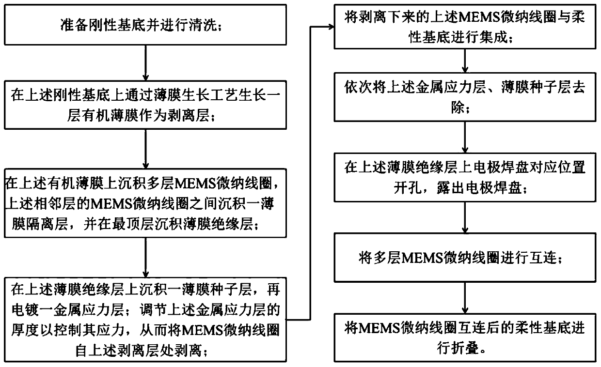
[0050] Such as figure 1 As shown, in one of the embodiments of the present application, a method for flexible heterogeneous integration of high-density MEMS micro-nano coils, the method includes the following steps:

[0051] Step 1, preparing the rigid base 1 and cleaning it.

[0052] Wherein, in this embodiment, the above-mentioned rigid substrate 1 can adopt silicon wafer or glass, etc., such as figure 2 shown.

[0053] Specifically, in this embodiment, a four-inch, double-sided polished clean silicon wafer or glass can be prepared.

[0054] Step 2, grow a peeling layer 2 on the rigid substrate 1 through a thin film growth process, such as image 3 shown.

[0055] Wherein, the film growth process includes: chemical vapo...


PUM


Abstract

The invention discloses a high-density MEMS micro-nano coil flexible heterogeneous integration method. The method comprises the steps: preparing and cleaning a rigid substrate; growing a stripping layer on the rigid substrate; depositing a plurality of layers of MEMS micro-nano coils on the stripping layer, depositing a thin film isolation layer between the MEMS micro-nano coils of adjacent layers, interconnecting the plurality of layers of MEMS micro-nano coils, and depositing a thin film insulation layer on the topmost layer; depositing a thin film seed layer on the thin film insulating layer, and then electroplating a metal stress layer; adjusting the thickness of the metal stress layer, and stripping the MEMS micro-nano coil; integrating the MEMS micro-nano coil and the flexible substrate; sequentially removing the metal stress layer and the film seed layer; forming a hole in the thin film insulating layer; and interconnecting and folding the multiple layers of MEMS micro-nano coils. According to the method, the multiple layers of interconnected MEMS micro-nano coils on the rigid substrate are transferred to the flexible substrate through a controllable stripping method, and the flexible substrate is folded to form a multi-layer stacked structure, so that the number of turns of the coils is greatly increased, and the problem of low output voltage of the MEMS electromagneticenergy collector in a narrow space is solved.

Description

technical field [0001] The application belongs to the field of micro-electromechanical system (MEMS) technology and micro-energy collection technology, and specifically relates to a method for flexible heterogeneous integration of high-density micro-nano coils. Background technique [0002] With the development of Internet of Things technology, various sensor devices are increasingly miniaturized and integrated. How to continuously supply energy to these miniature sensor devices has always been a difficult problem for researchers. The traditional pre-charging energy supply method has problems such as short battery life and environmental pollution. Fortunately, the rapid development of microelectronics technology and low power consumption technology has continuously reduced the power consumption of electronic devices, from the previous mW level to the uW level; it is predicted that it will drop to the nW level in the future. Therefore, energy in the environment can be harves...

Claims


Application Information

Patent Timeline
Patent Type & Authority Applications(China)
IPC IPC(8): B81B7/02B81C1/00
CPCB81B7/02B81C1/00349
Inventor 何剑丑修建穆继亮侯晓娟赵越芳范雪明张宁李春成陈亮薛峰赵浚东
Owner ZHONGBEI UNIV
Learn More