
Stator punching sheet and concentrated winding stator

A technology of stator punching and concentrated winding, which is applied in the direction of electric components, magnetic circuit shape/style/structure, electrical components, etc., can solve the problems of torque fluctuation, increase processing difficulty, processing difficulty and high cost, and reduce electromagnetic noise and vibration, improve the stability of work, and improve the effect of control accuracy

Pending Publication Date: 2020-06-23
GUANGDONG WINONE ELEVATOR
View PDF3 Cites 2 Cited by
  • Summary
  • Abstract
  • Description
  • Claims
  • Application Information

AI Technical Summary

Problems solved by technology

[0005] One solution is to change the shape of the rotor, by processing plum-shaped silicon steel sheets, stacking them and pressing them into a rotor with uniformly distributed protrusions on the side wall, and then installing the magnetic steel on the protrusions , can play a role in adjusting the back EMF waveform distortion, but this method is only suitable for rotors formed by pressing silicon steel sheets, such as inner rotor motors or small outer rotor motors, in large outer rotor motors, such as elevator traction On the machine or other heavy-duty traction machines, because the outer rotor is cast, it is impossible to set a large number of protrusions on the inside. Under this constraint, some manufacturers have chosen another improvement plan, namely Repairing the surface shape of magnetic steel, for example, the patent document CN202435155U provides a kind of wire cutting and cutting processing on the surface of magnetic steel to form a non-standard arc surface composed of a middle arc and tangent arcs on both sides The processing method is used to solve the problems of torque ripple and cogging torque, but this processing method needs to cut each magnet, which is made of precious rare metals such as praseodymium neodymium, dysprosium iron and other rare earth materials Composition, the material has high hardness, high processing difficulty and cost, and the waste of cutting waste is high, so when this type of structure is applied to a large traction machine, it greatly reduces the utilization rate of raw materials and increases the processing difficulty
[0006] In order to meet the good operation of the centralized winding and reduce the processing difficulty and cost of the rotor, the document with the notification number CN102801228A provides a stator punching structure, through the improvement of the outer edge of the teeth of the stator punching, through The straight line section in the middle and the tangential arc sections on both sides form the outer edge of the tooth, which is used to adjust the harmonic pulsation and improve the torque and efficiency. However, according to the structure and parameters in its technical plan, it improves the torque and Efficiency essentially solves the problems of torque fluctuation and harmonics, and does not solve the adjustment of back EMF waveform and air gap magnetic field waveform well.
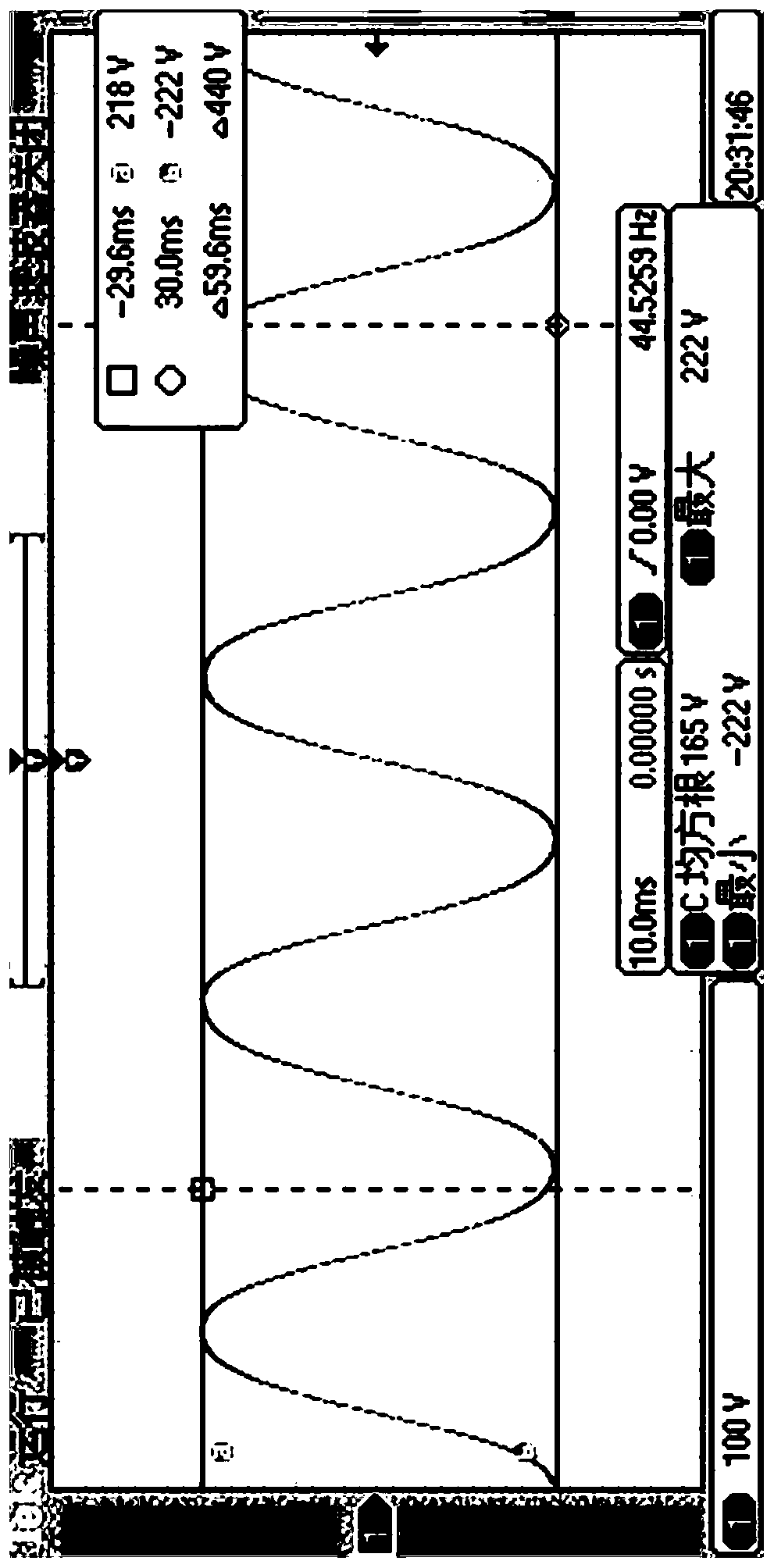
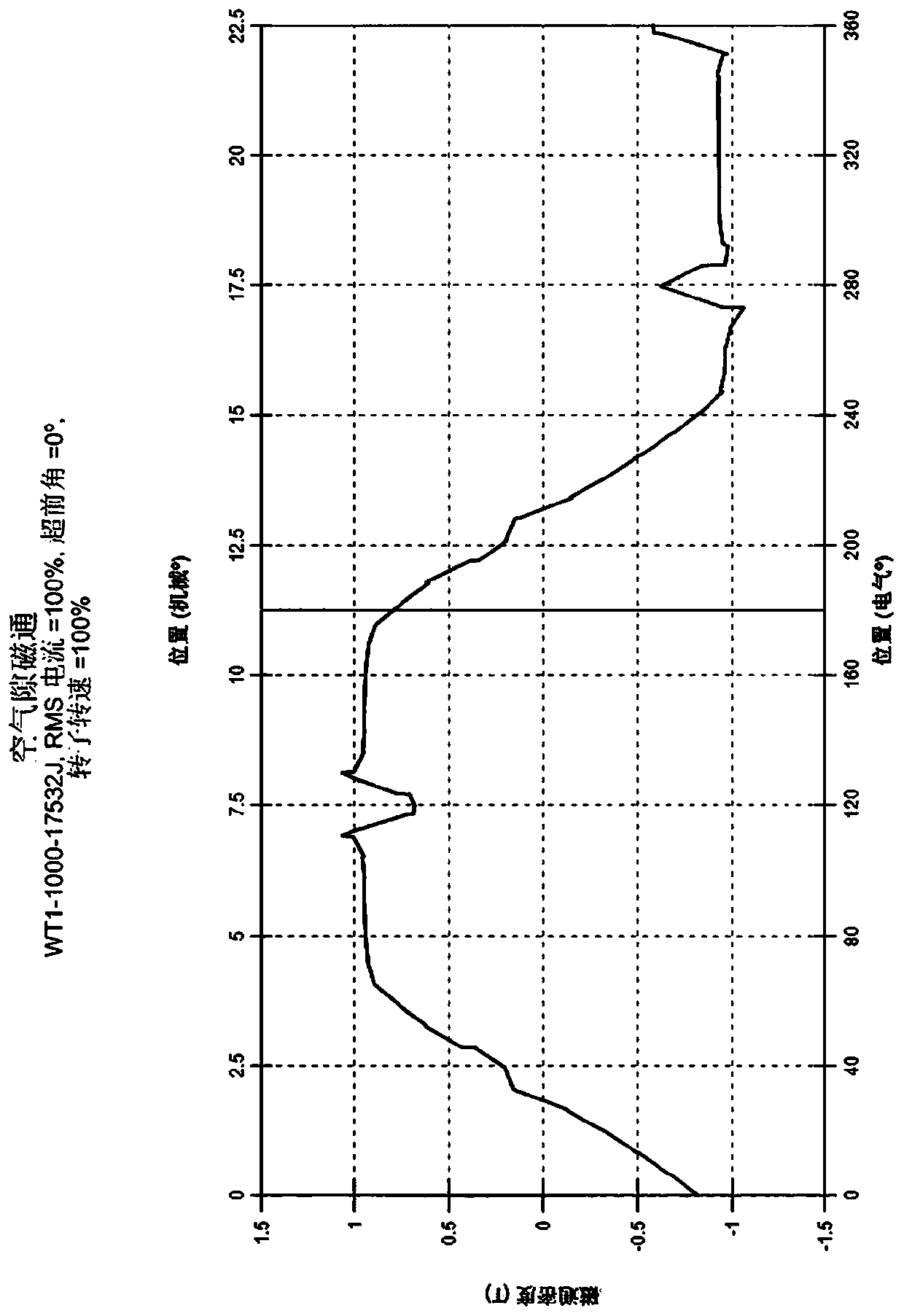
[0007] In addition, a stator structure is disclosed in the U.S. patent document with the publication number US 2011 / 0304238A1, the edges of the teeth are composed of a circular arc in the middle and tangent circular arcs on both sides, as in the document Figure 4 As shown, the stator of this structure is used to control the waveform of the back EMF to keep it sinusoidal, as shown in the figure, thereby reducing noise and vibration, but because its technical solution is suitable for small motors in hard disks, there is no adjustment gas The technical scheme of the gap magnetic field waveform, and by figure 1 and image 3 as well as Image 6 and Figure 8 It can be seen from the comparison that whether the waveform of the back EMF is sinusoidal or not is not necessarily related to that of the air gap magnetic field waveform. Image 6 The overall trend of the back EMF waveform in is sinusoidal, but the air gap magnetic field waveform is far from sinusoidal

Method used


Image

  • Stator punching sheet and concentrated winding stator
  • Stator punching sheet and concentrated winding stator
  • Stator punching sheet and concentrated winding stator

Examples


Embodiment Construction

[0055] The first to fifth embodiments of the present invention provide stator blanks with the first structure.

[0056] Such as Figure 11 As shown, the stator stamping of the first embodiment includes a tooth stamping 1a and a yoke stamping 2a integrated with the tooth stamping 1a, the yoke stamping 2a has a ring structure, and the tooth stampings 1a are equiangularly distributed In the T-shaped structure on the outside of the yoke punching piece 2a, the outer edge of each tooth punching piece 1a has a first arc edge 3a in the middle and is located on both sides of the middle arc segment 3a, tangent to the first arc edge 3a The second circular arc side 4a of the tooth part punching piece 1a is a parallel straight side edge 5a on both sides of the middle part, the center of the first circular arc side 3a is located on the centerline 6a of the tooth part punching piece, and the second arc The center of the side 4a is located on the 1 / 3.5 dividing line 7a of the middle side edg...


PUM


Abstract

The invention relates to the field of motors, and particularly relates to a stator punching sheet and a concentrated winding stator used in a heavy-load permanent magnet synchronous traction motor. The stator punching sheet and the stator comprise a tooth punching sheet and a yoke punching sheet integrated with the tooth punching sheet. Each tooth punching sheet is provided with a first arc edge and a second arc edge; the circle center of the first arc edge is located on the center line of the tooth punching sheet. The circle center of the second arc edge is located between 1 / 4.5-1 / 3.5 bisectors from the side edge of the middle part of the tooth punching sheet on the corresponding side to the direction of the center line of the tooth punching sheet. The radius length of the first arc edgeranges from 150mm to 300mm, the radius length of the second arc edge ranges from 60mm to 20mm, and the arc length ratio of the first arc edge to the second arc edge ranges from 1.7:1 to 1.9:1. By controlling the radius ratio, the arc length ratio and the circle center position between the arc surfaces, the requirements of reducing the electromagnetic noise and vibration of the motor, improving thecontrol precision of the motor, reducing the loss and improving the working stability are met at the same time.

Description

technical field [0001] The invention relates to the field of motors, in particular to a stator punch and a concentrated winding stator used in a large-load permanent magnet synchronous traction motor. Background technique [0002] Among the structural components of permanent magnet synchronous traction motors, the stator is an important component for generating a magnetic field. The stator generally includes an iron core and windings. There are generally two ways of winding setting: concentrated winding and distributed winding. When the motor is running, there are several parameters that are important criteria for considering the efficiency and stability of the motor. These parameters include back EMF waveform, back EMF harmonic, air gap magnetic field waveform, air gap magnetic field harmonic and torque ripple. In general, it is generally required that the back EMF waveform and the air gap magnetic field waveform are close to the sine wave, the back EMF harmonic and the air...

Claims


Application Information

Patent Timeline
Patent Type & Authority Applications(China)
IPC IPC(8): H02K1/14H02K29/03
CPCH02K1/146H02K1/148H02K2213/03H02K29/03
Inventor 杜秋邓轶华戴命夫张军锋朱昊江建平
Owner GUANGDONG WINONE ELEVATOR
Learn More