
Steel sheet member and method for producing the same

A manufacturing method and technology of steel plates, applied in the direction of manufacturing tools, vehicle parts, forming tools, etc., can solve the problems of complexity and large-scale

Active Publication Date: 2020-06-23
TOYOTA JIDOSHA KK
View PDF11 Cites 0 Cited by
  • Summary
  • Abstract
  • Description
  • Claims
  • Application Information

AI Technical Summary

Problems solved by technology

The steel plate member disclosed in Japanese Patent Laid-Open No. 2003-312534 has a corrugated structure, so it becomes complicated and large

Method used


Image

  • Steel sheet member and method for producing the same
  • Steel sheet member and method for producing the same
  • Steel sheet member and method for producing the same

Examples


no. 1 approach

[0033] Manufacturing method of steel plate member

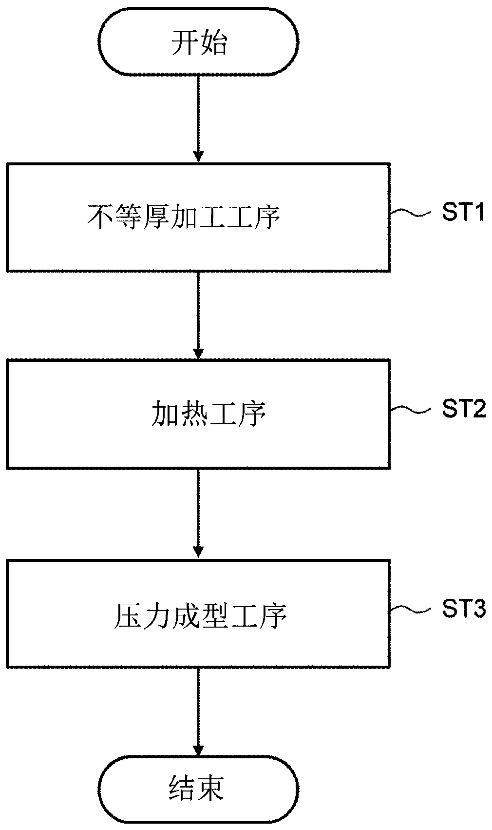
[0034] First, refer to figure 1 , the manufacturing method of the steel plate member of the first embodiment will be described. The method for manufacturing a steel plate member according to the first embodiment is preferable as a method for manufacturing a steel sheet member for automobiles requiring both high strength and excellent impact absorption properties. Examples of steel plate members include vehicle members having a hat-shaped cross section perpendicular to the longitudinal direction, such as side members (for example, front side members, rear floor side members), and pillars.

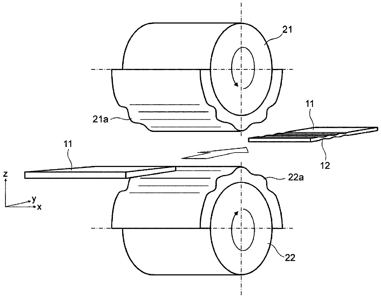
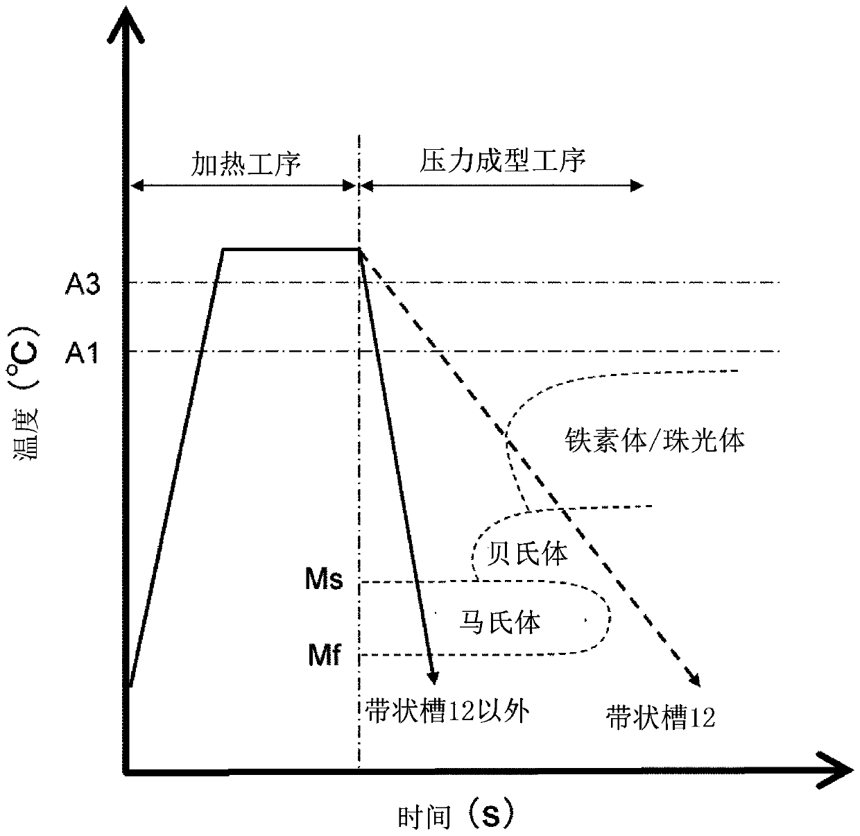
[0035] figure 1 It is a flowchart which shows the manufacturing method of the steel plate member of 1st Embodiment. Such as figure 1 As shown, the manufacturing method of the steel plate member according to the first embodiment includes the unequal thickness processing step (step ST1 ), the heating step (step ST2 ), and the press formin...

Embodiment

[0084] Hereinafter, examples of the steel plate member of the first embodiment will be described. The steel plate member of embodiment is as Figure 6 The plate-shaped steel member shown. First, the strip-shaped groove 12 is formed in a steel plate for hot stamping made of manganese-boron steel (22MnB5 steel) having a thickness of 2.0 mm, a width of 50 mm, and a length of 165 mm. Then, after holding the steel sheet at 900° C. for one minute to austenitize the entire steel sheet, the steel sheet was sandwiched between dies (upper die and lower die) to perform quenching.

[0085] Figure 12 It is a longitudinal sectional view and a photograph of a microstructure of a steel plate member of an example. Such as Figure 12 As shown, two pairs of strip-shaped grooves 12 with isosceles trapezoidal cross-sections are provided oppositely on the upper and lower surfaces. The width of the bottom surface of the strip-shaped groove 12 was set to 15 mm, and the width of the upper surfac...


PUM

PropertyMeasurementUnit
Thicknessaaaaaaaaaa
Thicknessaaaaaaaaaa
Vickers hardnessaaaaaaaaaa

Abstract

A steel sheet member and a method for producing the same. The method includes: forming at least one pair of opposing strip grooves in a flat steel sheet such that one of the pair of opposing strip grooves is disposed in one of opposite surfaces of the steel sheet, the other of the pair of opposing strip grooves is disposed in the other of the opposite surfaces, and the strip grooves extend in a direction crossing a longitudinal direction of the steel sheet; heating the steel sheet having the strip grooves to a temperature higher than an austenite transformation finish temperature; and placingthe heated steel sheet between an upper die and a lower die to press-form the steel sheet while cooling. When press-forming the steel sheet while cooling, there is space between each of the upper andlower dies and a bottom of a corresponding one of the strip grooves.

Description

technical field [0001] The invention relates to a steel plate component and a manufacturing method thereof. Background technique [0002] In recent years, structural members for automobiles, such as side members, are desired to have high strength and to have excellent impact absorption characteristics. JP 2003-312534 discloses a technique in which a part of a steel plate member having a hat-shaped cross section has a corrugated structure in order to improve shock absorption characteristics. [0003] The inventors have found the following points regarding the steel plate member and its manufacturing method. Since the steel plate member disclosed in JP 2003-312534 has a corrugated structure, it becomes complicated and large. Contents of the invention [0004] The present invention provides a steel plate member having a simple and compact configuration and excellent shock absorption properties and a method of manufacturing the same. [0005] A first aspect of the present i...

Claims


Application Information

Patent Timeline
IPC IPC(8): B21D13/02B21D13/04B21D37/16B21D53/88
CPCB21D13/02B21D13/04B21D37/16B21D53/88C21D9/46B21D22/022B21D35/006C21D2211/001Y10T428/12201
Inventor 伊原智章
Owner TOYOTA JIDOSHA KK
Learn More