


Quick Research
Generate reliable direction feasibility study reports for your R&D in just a few steps.

Technical Q&A
Discover and master advanced knowledge NOW. Basics, ideas, possibilities, all at once.

Find Solutions
As an expert in R&D theories, this can generate solutions to your technical problems instantly.

Evaluate Feasibility
Analyze your overall solution with one click, know your potential R&D risks in advance.

Monitor Landscape
Get weekly tech updates, stay abreast of the latest tech innovations and key insights.
Intelligent substation optical fiber link testing method and device
A technology of intelligent substation and optical fiber link, applied in circuit devices, electrical components, electromagnetic wave transmission systems, etc., can solve the problems of low test efficiency and low precision, and achieve the effect of shortening the test period, fast response speed, and improving test efficiency.
- Summary
- Abstract
- Description
- Claims
- Application Information
AI Technical Summary
Problems solved by technology
Method used
Image

Examples
Embodiment 1
[0049] This embodiment provides a method for testing an optical fiber link in a smart substation, including:
[0050] Step 1, analyze the SCD file of the smart substation to obtain the virtual and real link mapping relationship of the optical fiber link of the device under test;
[0051]Step 2, receiving the optical signal containing the GOOSE message or the SV message sent by the optical port of the device under test through the optical fiber, and analyzing and testing the optical signal to obtain the transmission optical power of the optical port of the device under test;
[0052] Step 3: Send an optical signal containing a GOOSE message or an SV message to the optical port of the device under test through an optical fiber, and gradually adjust the optical power attenuation value of the optical port under test through the dichotomy method. , the measured optical power received by the tested optical port of the device under test is the light receiving sensitivity of the devic...
Embodiment 2
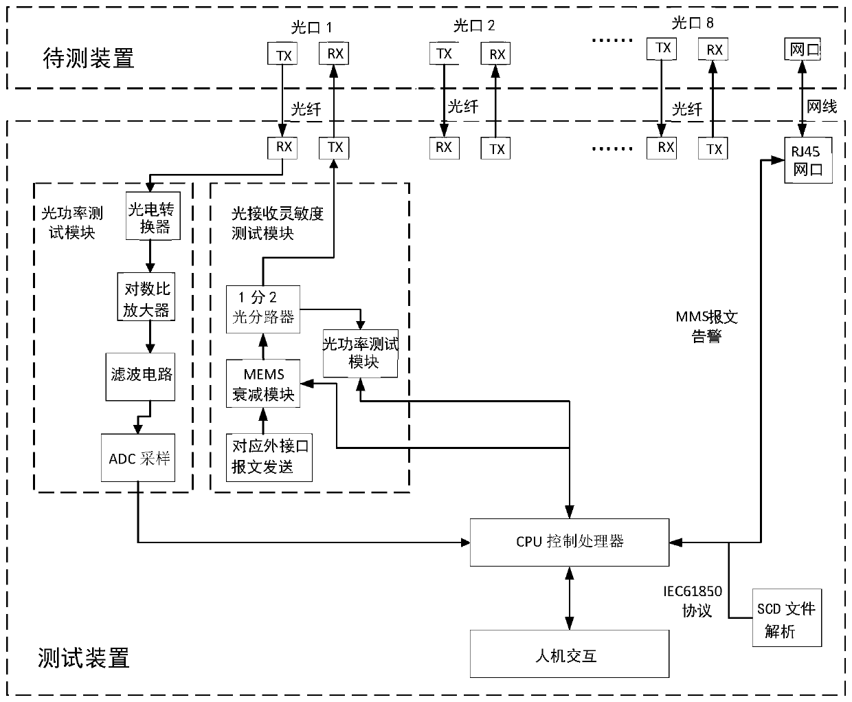
[0066] This embodiment provides a smart substation optical fiber link test device, the test device is connected to the measured optical port of the device under test through an optical fiber, and is used for the transmission of optical signals; the test device is connected to the network port of the device under test through a network cable Connect, be used for the transmission of station control layer MMS message; Described test device comprises:
[0067] The SCD file analysis module is used to analyze the SCD file of the smart substation, and obtain the virtual and real link mapping relationship of the optical fiber link of the device under test;
[0068] The optical power test module is used to receive the optical signal containing the GOOSE message or SV message sent by the optical port of the device under test through the optical fiber, and analyze and test the optical signal to obtain the transmission of the optical port of the device under test. Optical power;
[0069]...
PUM
 Abstract
Description
Claims
Application Information
 - R&D Engineer
- R&D Manager
- IP Professional
- Industry Leading Data Capabilities
- Powerful AI technology
- Patent DNA Extraction
Browse by: Latest US Patents, China's latest patents, Technical Efficacy Thesaurus, Application Domain, Technology Topic, Popular Technical Reports.
© 2024 PatSnap. All rights reserved.Legal|Privacy policy|Modern Slavery Act Transparency Statement|Sitemap|About US| Contact US: help@patsnap.com