


Quick Research
Generate reliable direction feasibility study reports for your R&D in just a few steps.

Technical Q&A
Discover and master advanced knowledge NOW. Basics, ideas, possibilities, all at once.

Find Solutions
As an expert in R&D theories, this can generate solutions to your technical problems instantly.

Evaluate Feasibility
Analyze your overall solution with one click, know your potential R&D risks in advance.

Monitor Landscape
Get weekly tech updates, stay abreast of the latest tech innovations and key insights.
Automatic gain control circuit and its automatic attenuating circuit and variable attenuater
An automatic attenuation and attenuator technology, which is applied in the direction of gain control, amplification control, electrical components, etc., can solve the problem that the automatic attenuation circuit cannot be applied, and achieve the effect of cost saving and large attenuation range
- Summary
- Abstract
- Description
- Claims
- Application Information
AI Technical Summary
Problems solved by technology
Method used
Image

Examples
Embodiment Construction
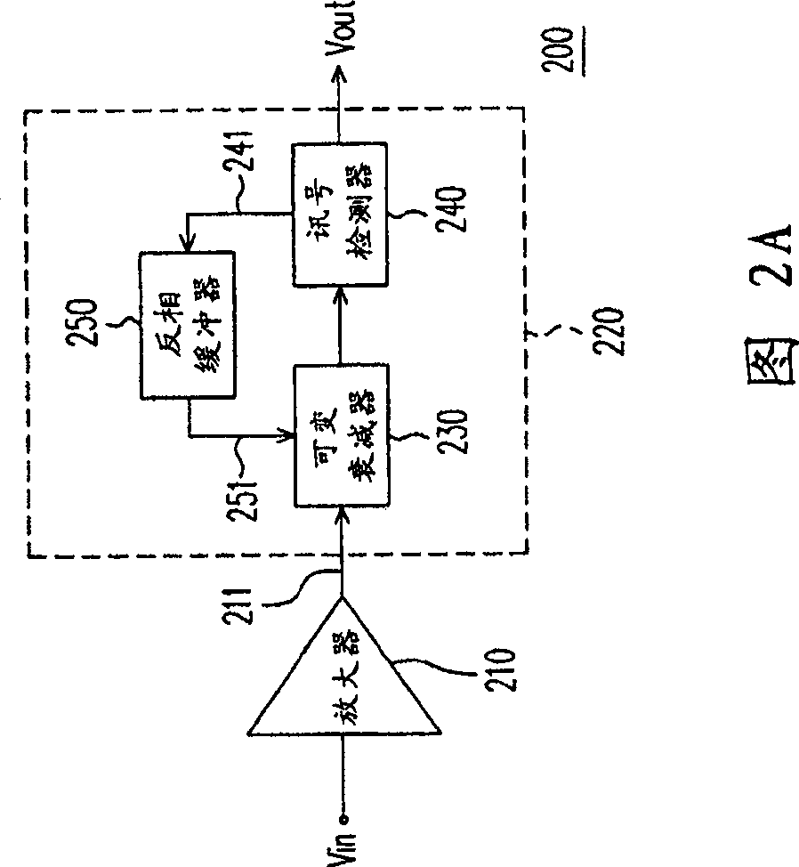
[0048]FIG. 2A is a block diagram of an automatic gain control circuit according to an embodiment of the present invention. Please refer to FIG. 2A , for the convenience of describing the present invention, in this embodiment, the automatic gain control circuit 200 is applied in a wireless transmission system, for example. In different environments and conditions, the input signal (Vin) obtained by the wireless transmission system is often unstable, so the automatic gain control circuit 200 is required to automatically change the system gain to generate a stable signal (ie, the output signal Vout in the figure) .
[0049] The automatic gain control circuit 200 includes an amplifier 210 and an automatic attenuation circuit 220 . The amplifier 210 amplifies (gains) the unstable input signal Vin by a predetermined fixed ratio and outputs the input signal 211, and then the automatic attenuation circuit 220 appropriately attenuates the amplified input signal 211 according to the si...
PUM
 Abstract
Description
Claims
Application Information
 - R&D Engineer
- R&D Manager
- IP Professional
- Industry Leading Data Capabilities
- Powerful AI technology
- Patent DNA Extraction
Browse by: Latest US Patents, China's latest patents, Technical Efficacy Thesaurus, Application Domain, Technology Topic, Popular Technical Reports.
© 2024 PatSnap. All rights reserved.Legal|Privacy policy|Modern Slavery Act Transparency Statement|Sitemap|About US| Contact US: help@patsnap.com