Gain compensation method and device for a radio frequency module

A technology of radio frequency module and gain compensation, which is applied in the field of radio frequency, can solve the problems of being unable to be more accurate, and achieve the effect of large supplementary range and high precision

Active Publication Date: 2018-05-18
GCI SCI & TECH
View PDF9 Cites 0 Cited by
  • Summary
  • Abstract
  • Description
  • Claims
  • Application Information

AI Technical Summary

Problems solved by technology

The accuracy of RF gain compensation depends on the minimum step of the RF attenuator. At present, the minimum step of the RF attenuator of the RF device manufacturer is 0.5dB, which cannot be more accurate

Method used


Image

  • Gain compensation method and device for a radio frequency module

Examples


Embodiment Construction

[0049] The following will clearly and completely describe the technical solutions in the embodiments of the present invention with reference to the accompanying drawings in the embodiments of the present invention. Obviously, the described embodiments are only some, not all, embodiments of the present invention. Based on the embodiments of the present invention, all other embodiments obtained by persons of ordinary skill in the art without creative efforts fall within the protection scope of the present invention.

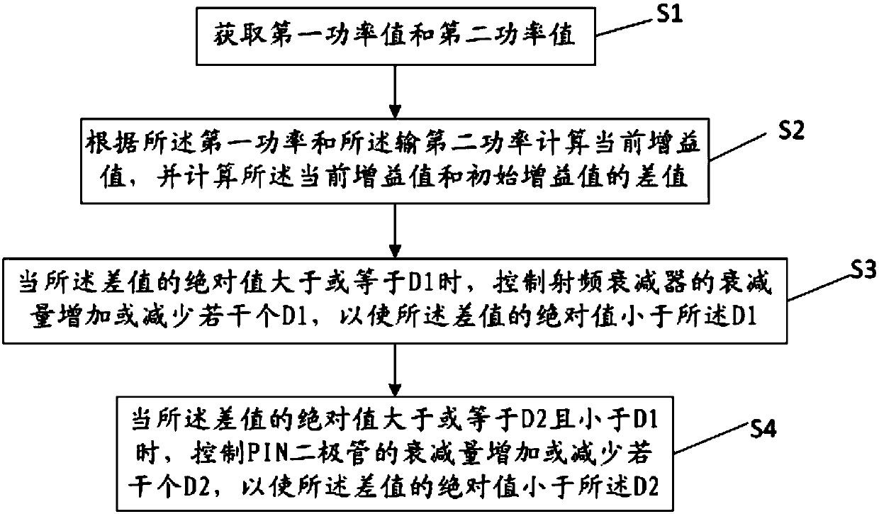
[0050] see figure 1 , is a schematic flowchart of a gain compensation method for a radio frequency module provided in an embodiment of the present invention, and the method includes the following steps:

[0051] S1. Obtain a first power value and a second power value; the first power value is the power value of the output signal of the front-end module of the radio frequency module, and the second power value is the power value of the output signal of the radio fre...


PUM


Abstract

The invention discloses a gain compensation method and device for a radiofrequency module. The method comprises steps of: acquiring a first power value and a second power value; computing a current gain value according to the first power value and the second power value and computing a difference value between the current gain value and an initial gain value; when the absolute value of the difference value is greater than or equal to 1, increasing or decreasing the attenuation of an radiofrequency attenuator by a plurality of D1s in order that the absolute value of the difference value is less than the D1; when the absolute value of the difference value is greater than or equal to D2 but less than D1, increasing or decreasing the attenuation of a PIN diode by a plurality of D2s in order that the absolute value of the difference value is less than the D2, wherein the D1 is the minimum attenuation precision of the radiofrequency attenuator, the D2 is the minimum attenuation precision of the PIN diode and is less than D1. The gain compensation method and device may increase radiofrequency gain compensation precision while guaranteeing a large enough radiofrequency gain compensation range.

Description

technical field [0001] The invention relates to the field of radio frequency technology, in particular to a gain compensation method and device for a radio frequency module. Background technique [0002] Radio frequency (Radio Frequency: RF) specifically refers to electromagnetic waves with a certain wavelength that can be used for radio communication. The high-frequency circuit used to generate radio frequency becomes a radio frequency circuit, which is basically composed of passive components, active devices and passive networks. With the development of communication technology, the frequency used by communication equipment is increasing day by day, radio frequency (RF) and microwave (MW) circuits are widely used in communication systems, and the field of radio frequency circuit design has received special attention from the industry. [0003] In the active transmitting\receiving system of radio frequency and microwave communication and LNA (low noise amplifier) ​​and PA ...

Claims


Application Information

Patent Timeline
Patent Type & Authority Patents(China)
IPC IPC(8): H03G3/30
CPCH03G3/3036
Inventor 赵栋
Owner GCI SCI & TECH
Why Eureka
Try Eureka