
Constant-temperature incubation system

A technology of constant temperature incubation and constant temperature module, which is used in chemical instruments and methods, preparation of test samples, laboratory utensils, etc., can solve the problems of unsuitable temperature control, waste of resources, and reduced market share during operation, and achieve convenient installation. The effect of commissioning and maintenance carrying, reducing design and processing costs, and improving product suitability

Active Publication Date: 2020-06-19
北京倍肯恒业科技发展股份有限公司
View PDF10 Cites 1 Cited by
  • Summary
  • Abstract
  • Description
  • Claims
  • Application Information

AI Technical Summary

Problems solved by technology

[0002] Existing constant temperature incubation equipment is nothing more than using an open flame with objects such as an alcohol lamp or an incubator (drying box) to directly carry out constant temperature incubation, or to use media such as water, oil, wind or heating sheets to carry out indirect constant temperature incubation, but The above method of constant temperature incubation not only has high requirements for the detection environment but also has certain defects.
For example, the use of open flames for constant temperature incubation not only requires special auxiliary equipment, but also the temperature during operation should not be controlled, and it is easy to cause fire or explosion hazards.
For example, the use of equipment such as incubators or drying boxes is not only expensive, but the machine is large and difficult to carry, and it is difficult to observe the changes of samples during the constant temperature process, and it is easy to cause temperature unevenness, sample composition or property changes when large batches of samples are incubated at constant temperature. The constant temperature cost of incubating a single sample with small batches is high
Another example is the use of media such as water, oil, wind, and heating fins. Not only must the sealing problem be considered in part of the structure, but also a container tank for heat dissipation should be left, and most of the heat will be lost in other places when the temperature is kept constant, which not only wastes resources but also The waiting time is still relatively long
[0003] In addition, constant temperature incubation equipment used in different industries or fields has poor compatibility and relatively single functions. For example, when dehydrating and drying fruits, vegetables, meat or other products in the food deep processing industry, some of them use different methods according to their processing technology and purpose. Raising the temperature forces the water in the food to evaporate and then achieves the desired purpose, while some use lowering the temperature to force the cell wall in the food to rupture to achieve the purpose of dehydration
This kind of equipment that can both heat and cool is often two different types of equipment. Even if it is integrated into the same equipment, it is often two systems that cannot appear or work at the same time.
This will not only cause waste of resources, but also reduce production efficiency. When users choose equipment, they often have to make a trade-off between heating and cooling before choosing, thereby reducing market share.

Method used


Image

  • Constant-temperature incubation system
  • Constant-temperature incubation system
  • Constant-temperature incubation system

Examples


Embodiment Construction

[0032] The specific embodiments of the present invention will be described in detail below in conjunction with the accompanying drawings, but it should be understood that the protection scope of the present invention is not limited by the specific embodiments.

[0033] Unless expressly stated otherwise, throughout the specification and claims, the term "comprise" or variations thereof such as "includes" or "includes" and the like will be understood to include the stated elements or constituents, and not Other elements or other components are not excluded.

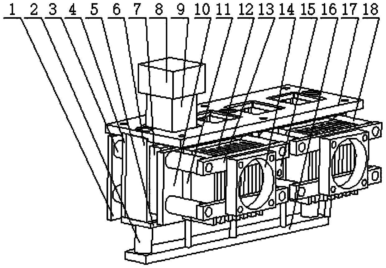
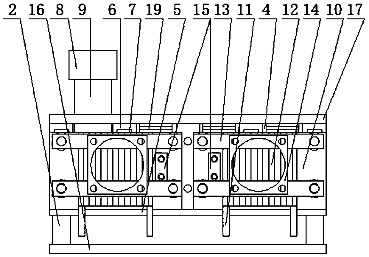
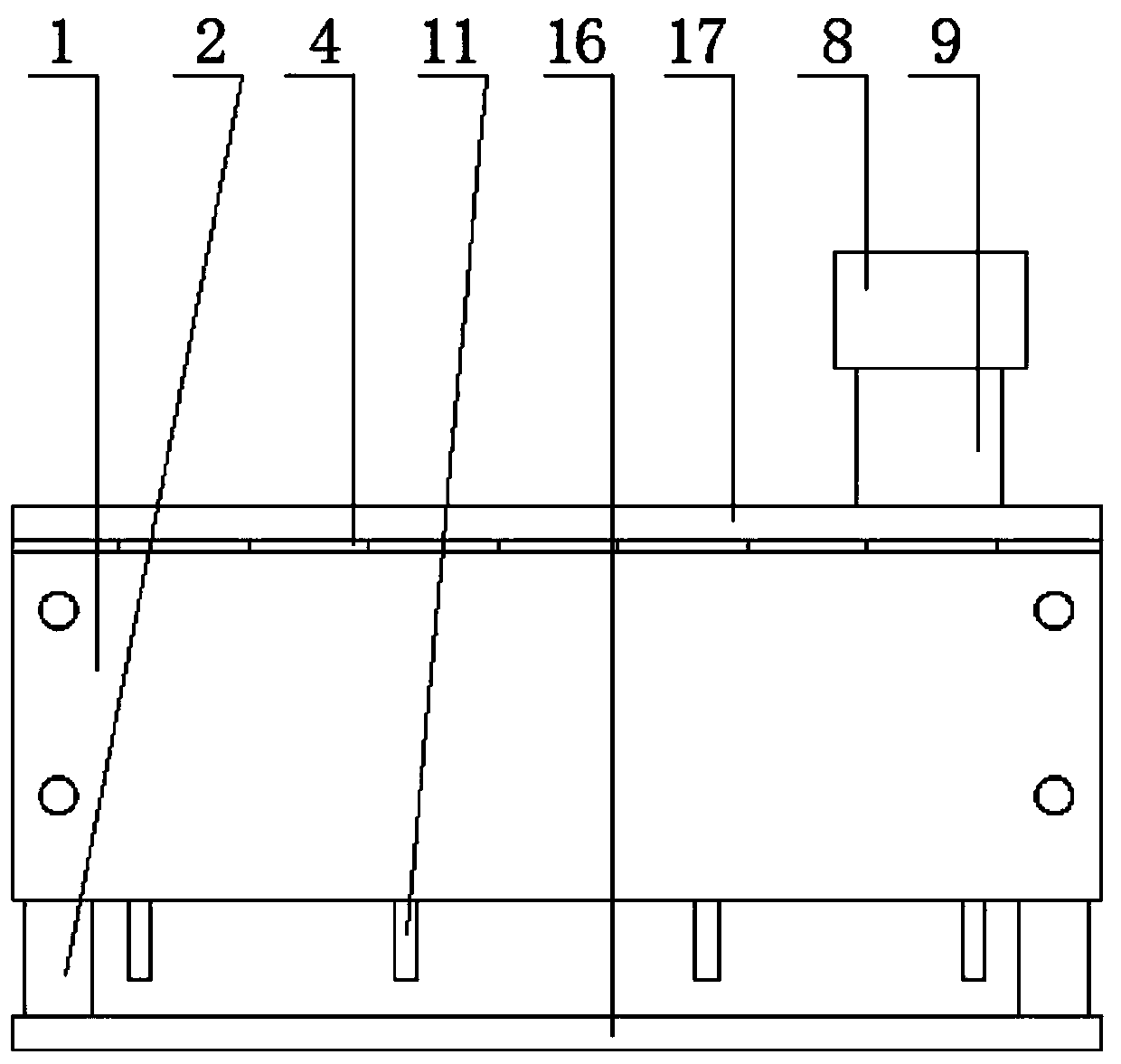
[0034] like Figure 1 to Figure 4 As shown, the specific structure of the constant temperature incubation system according to the preferred embodiment of the present invention includes: a main control board 1 , a plurality of incubation units and a container 9 .

[0035]Wherein, each incubation unit includes: a rack, a graphene thermal conductive plate 10 , a constant temperature module 11 , a heat sink 12 , a temperature ...


PUM

PropertyMeasurementUnit
Thicknessaaaaaaaaaa

Abstract

The invention discloses a constant-temperature incubation system. The constant-temperature incubation system comprises a container and incubation units. Each incubation unit comprises a rack, a graphene heat conduction plate, a constant temperature module, a cooling fin, a temperature feedback circuit board and an upper cover; a container groove is formed in an upper cover. Each graphene heat conduction plate is arranged on the side surface of a container groove. Each constant temperature module abuts against each graphene heat conduction plate. Each cooling fin is arranged on the outer side of each constant-temperature module. Each temperature feedback circuit board is integrated with each temperature sensor and is arranged on the side surface of each graphene heat conduction plate; and each main control board comprises a heating control module and a communication module, and each heating control module is connected with each constant temperature module and the temperature feedback circuit board of each incubation unit through the communication module to form a temperature closed-loop control system of each incubation unit. The constant-temperature incubation system can carry outindependent closed-loop control on the constant-temperature module of each incubation unit so as to realize accurate control on different constant-temperature incubation temperatures of different samples or products.

Description

technical field [0001] The invention relates to the field of incubation equipment, in particular to a constant temperature incubation system. Background technique [0002] Existing constant temperature incubation equipment is nothing more than using an open flame with objects such as an alcohol lamp or an incubator (drying box) to directly carry out constant temperature incubation, or to use media such as water, oil, wind or heating sheets to carry out indirect constant temperature incubation, but The method of adopting the above-mentioned constant temperature incubation not only has higher requirements on the detection environment but also has certain defects. For example, the use of open flames for constant temperature incubation not only requires special auxiliary equipment, but also the temperature during operation is not suitable to be controlled, and it is easy to cause fire or explosion hazards. For example, the use of equipment such as incubators or drying boxes is ...

Claims


Application Information

Patent Timeline
IPC IPC(8): G01N1/44B01L7/00
CPCG01N1/44B01L7/00
Inventor 刘光中高鲁嘉丁绍伟张学治
Owner 北京倍肯恒业科技发展股份有限公司
Learn More