
Photocatalytic fiber purification device in long and narrow space and using method thereof

A purification device and photocatalytic technology, applied in the field of environmental purification, can solve the problems of photocatalyst catalytic effect discount, easy loss of nano powder, uncontrollable catalytic efficiency, etc., achieve high light energy utilization efficiency, reduce light distribution requirements, light The effect of small mass transfer resistance

Inactive Publication Date: 2020-06-19
FOSHAN JINJINGCHUANG ENVIRONMENTAL PROTECTION TECH CO LTD
View PDF0 Cites 0 Cited by
  • Summary
  • Abstract
  • Description
  • Claims
  • Application Information

AI Technical Summary

Problems solved by technology

[0005] At present, photocatalysts, especially nano-titanium dioxide particles, are widely used in various environmental purification treatments, but because titanium dioxide must rely on good light, especially ultraviolet light, to achieve good catalytic effects, in some narrow and long spaces, For example, in deep wells, tunnels, etc., it is difficult to arrange sufficient light sources, and the catalytic effect of photocatalysts is greatly reduced.
Conventional granular powder photocatalysts, nano-powders are easy to lose, easy to agglomerate, and pose health risks to the human body. Therefore, nano-titanium dioxide particles are generally loaded on the carrier, but the conventional surface coating is easy to be adhered by dirt, resulting in reduced catalytic efficiency. , and the catalytic efficiency is uncontrollable

Method used


Image

  • Photocatalytic fiber purification device in long and narrow space and using method thereof
  • Photocatalytic fiber purification device in long and narrow space and using method thereof
  • Photocatalytic fiber purification device in long and narrow space and using method thereof

Examples


Embodiment Construction

[0047] The following will clearly and completely describe the technical solutions in the embodiments of the present invention with reference to the accompanying drawings in the embodiments of the present invention. Obviously, the described embodiments are only some, not all, embodiments of the present invention. Based on the embodiments of the present invention, all other embodiments obtained by persons of ordinary skill in the art without making creative efforts belong to the protection scope of the present invention.

[0048] In the following description, many specific details are set forth in order to fully understand the present invention, but the present invention can also be implemented in other ways different from those described here, therefore, the protection scope of the present invention is not limited by the specific implementation disclosed below. Example limitations.

[0049]In describing the present invention, it should be understood that the terms "center", "lo...


PUM


Abstract

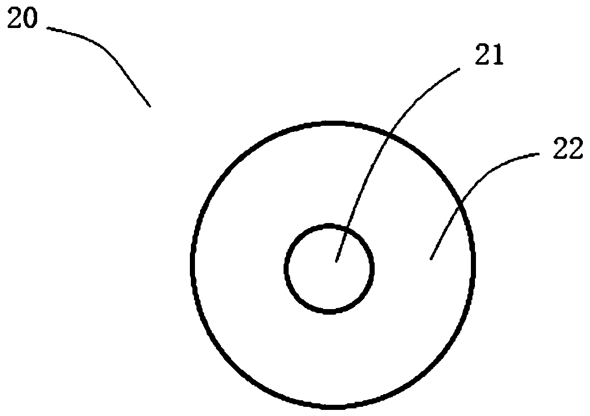
The invention discloses a photocatalytic fiber purification device in a long and narrow space. Sewage or air is purified and treated through the photocatalytic fibers; the photocatalytic fiber purification device comprises a shell, a plurality of photocatalytic fibers connected with the shell, a stretching plate fixed to the other end of the photocatalytic fibers, and a winding assembly. The photocatalytic fiber is of a skin-core structure and comprises a core layer and a skin layer wrapping the core layer, the core layer at least comprises transparent resin, and the skin layer at least comprises a transparent fiber-forming high polymer and nano titanium dioxide particles mixed into the transparent fiber-forming high polymer. The environment is purified through the photocatalytic fibers exposed in the long and narrow space, and titanium dioxide particles are not prone to loss, relatively fixed and not prone to agglomeration; meanwhile, the exposure rate of the titanium dioxide particles can be increased by stretching the photocatalytic fibers, the environment is continuously purified within a certain period of time, and the catalytic reaction is controlled to a certain extent.

Description

technical field [0001] The invention relates to the technical field of environmental purification, in particular to a photocatalytic fiber purification device in a long and narrow space and a use method thereof. Background technique [0002] Environmental purification refers to the purification of water environment or gas environment, through various biochemical means to make various indicators reach specific standards, so as to protect the ecological environment and human health. [0003] A photocatalyst is a substance that does not change itself under the irradiation of light, but can promote chemical reactions. Photocatalyst converts light energy into chemical reaction energy, produces catalysis, and excites surrounding water molecules and oxygen into highly oxidative hydroxyl radicals and superoxide ion radicals, which can decompose organic substances that are harmful to the human body and the environment. Substances and some inorganic substances, accelerate the reactio...

Claims


Application Information

Patent Timeline
IPC IPC(8): C02F1/30B01D53/86B01D53/74
CPCB01D53/74B01D53/86B01D2255/20707B01D2255/802C02F1/30C02F2201/002C02F2305/10
Inventor 张国基张希兰汤燕雯赵甜
Owner FOSHAN JINJINGCHUANG ENVIRONMENTAL PROTECTION TECH CO LTD
Learn More