
Axial liquid flushing micro electrolytic machining device and machining method

A micro-electrolysis and processing device technology, applied in the direction of electrochemical processing equipment, the supply of processing working medium, metal processing equipment, etc., can solve the problems of limited processing depth, reduced processing accuracy, and difficulty in discharging electrolytic products, and achieve low cost , high efficiency and low effect

Active Publication Date: 2021-05-18
INST OF MACHINERY MFG TECH CHINA ACAD OF ENG PHYSICS
View PDF6 Cites 0 Cited by
  • Summary
  • Abstract
  • Description
  • Claims
  • Application Information

AI Technical Summary

Problems solved by technology

However, it is more difficult to manufacture electrodes with microstructure flutes; the method of lateral flushing is likely to cause electrode vibration, so the flushing speed is limited and the processing depth is still limited; the repetitive feeding caused by electrode retraction will reduce Machining accuracy; the method of electrode eccentric trajectory movement is not suitable for processing micro-holes with small diameters; the method of high-pressure flushing of hollow electrodes is limited by the outer diameter of hollow electrodes, and is not suitable for processing micro-holes with small diameters
[0004] At present, it is still necessary to solve the problems of difficult discharge of electrolytic products and slow renewal of electrolyte in micro-electrolytic machining

Method used


Image

  • Axial liquid flushing micro electrolytic machining device and machining method
  • Axial liquid flushing micro electrolytic machining device and machining method
  • Axial liquid flushing micro electrolytic machining device and machining method

Examples


Embodiment Construction

[0049] The present invention will be described in detail below in conjunction with the accompanying drawings and embodiments.

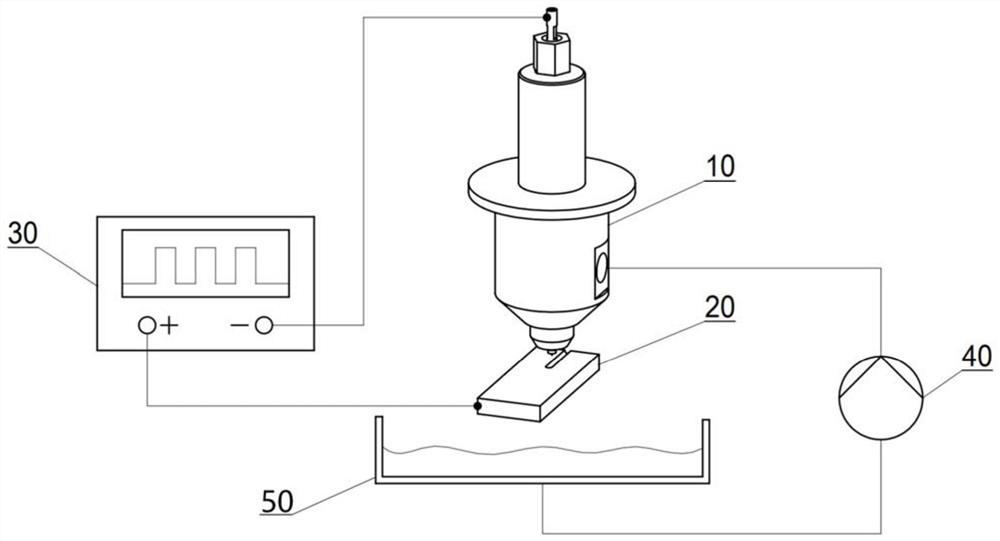
[0050] A micro-electrolytic processing device for axial liquid flushing, the processing device includes an axial liquid flushing tool head 10 , a workpiece anode 20 , a pulse power supply 30 , a booster pump 40 and an electrolyte tank 50 .

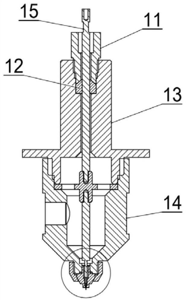
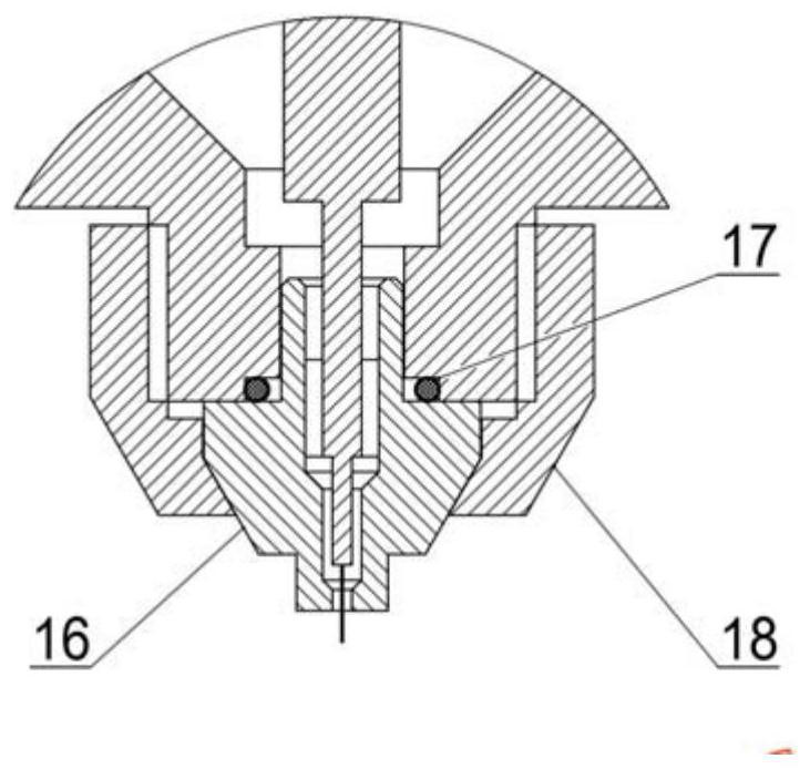
[0051] In a preferred embodiment, the axial flushing tool head 10 includes an upper cavity 13 , a lower cavity 14 , a combined electrode 15 , a nozzle 16 , and a pressing member II18.

[0052] The bottom of the upper cavity 13 is open, and the top of the upper cavity 13 has a through hole.

[0053]The axial flushing tool head 10 also includes a water stopper 12. The through hole of the upper cavity 13 is provided with an internal thread section, and the bottom of the internal thread section is provided with a water stopper annular step. The water stopper 12 is installed On the annular step of the water stopper in...


PUM

PropertyMeasurementUnit
diameteraaaaaaaaaa

Abstract

The invention discloses an axial flushing micro-electrolytic machining device and a machining method. Connect the upper end of the lead rod to the negative pole of the pulse power supply, and the anode of the workpiece to the positive pole of the pulse power supply, so that the machine tool drives the axial flushing tool head close to the anode of the workpiece, and there is a machining gap between the working end of the tool electrode and the surface of the anode of the workpiece. The pressure of the pressure pump makes the electrolyte flush to the workpiece anode machined surface along the axial direction of the tool electrode, so that electrolysis occurs between the tool electrode and the workpiece anode machined surface until fine features are obtained on the workpiece anode machined surface. The processing method and processing device can effectively promote the discharge of electrolysis products and heat in the processing gap, accelerate the renewal of the electrolyte, and at the same time avoid the deformation and vibration of the fine tool electrode caused by the non-axial flushing. The axial flushing micro-electrochemical processing device and processing method of the present invention can realize efficient processing of micro-structure features with small size and large aspect ratio.

Description

technical field [0001] The invention belongs to the technical field of micro electrolytic machining, and in particular relates to an axial flushing micro electrolytic machining device and a processing method. Background technique [0002] With the rapid development of industrial manufacturing, there are more and more demands for microstructure features in the fields of aerospace, medical, weaponry, and micro-devices. A large number of parts with microstructure features have been designed. higher requirement. The electrolytic machining method has the advantages of no tool loss, no burrs, no heat-affected zone, high efficiency, and is not affected by material strength and hardness, and can theoretically achieve atomic-level dissolution and removal of anode materials. Potential processing methods. [0003] Micro-electrolytic machining technology is an electrolytic machining method for micro-structural feature processing. It generally uses narrow pulse width, low voltage and s...

Claims


Application Information

Patent Timeline
Patent Type & Authority Patents(China)
IPC IPC(8): B23H3/00B23H3/10
CPCB23H3/00B23H3/10
Inventor 张勇斌荆奇李飘庭李建刘广民李建原张林严广和袁伟然胡波
Owner INST OF MACHINERY MFG TECH CHINA ACAD OF ENG PHYSICS
Learn More