
A method to improve the success rate of 3D printing thin-walled metal components

A metal component, 3D printing technology, applied in the direction of improving energy efficiency, process efficiency, additive manufacturing, etc., can solve problems such as labor cost increase, inability to accurately control warpage deformation of thin-walled metal components, repeated failures, etc. The effect of printing success rate and reducing the risk of scraper jamming

Active Publication Date: 2021-08-03
CHENGDU AIRCRAFT INDUSTRY GROUP
View PDF4 Cites 0 Cited by
  • Summary
  • Abstract
  • Description
  • Claims
  • Application Information

AI Technical Summary

Problems solved by technology

[0004] At present, the printing and manufacturing of complex thin-walled metal components is not only limited by the forming size of the equipment, but also the printing and manufacturing process is not yet mature, resulting in an increased probability of printing failure and repeated failures. It takes multiple iterations to find the best solution. This situation greatly increases the cost of equipment, raw materials and labor, which seriously restricts the development of this technology
[0005] The most critical reason for the failure of thin-walled metal components to print is the inability to accurately control their warping deformation during the printing process
Due to the high strength of metal materials, when deformation occurs due to heat concentration during the printing process, the deformed part is prone to jamming of the scraper, which can easily cause damage to the scraper and components, and eventually make the printing invalid

Method used


Image

  • A method to improve the success rate of 3D printing thin-walled metal components
  • A method to improve the success rate of 3D printing thin-walled metal components
  • A method to improve the success rate of 3D printing thin-walled metal components

Examples


Embodiment 1

[0028] This embodiment provides a method for improving the success rate of 3D printing thin-walled metal components, including the following steps:

[0029] (1) Perform pre-software processing on the digital model of thin-walled metal components, adjust the position of thin-walled metal components in the equipment forming cabin, and ensure that thin-walled metal components can be printed;

[0030] (2) Optimize the digital model of thin-walled metal components that meet the above requirements;

[0031] (3) Adjust the position of the thin-walled metal components to digitally import the parameter data package of the printing material, and then import the 3D printing equipment to prepare for the pre-printing of the equipment. After the preparation is completed, start printing through 3D printing technology;

[0032] (4) After the printing is completed, take out the thin-walled metal components for subsequent processing, and finally complete the delivery of the thin-walled metal co...

Embodiment 2

[0034] On the basis of the above embodiments, this embodiment further defines the material of the thin-walled metal component, the printing material used, and the 3D printing technology used. The thin-walled metal component for 3D printing is a large thin-walled titanium alloy component , the printing material used is titanium alloy TC4 powder, and the 3D printing technology used is laser selective melting forming technology. Other parts of this embodiment are the same as Embodiment 1 and will not be repeated here.

Embodiment 3

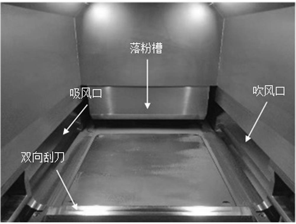
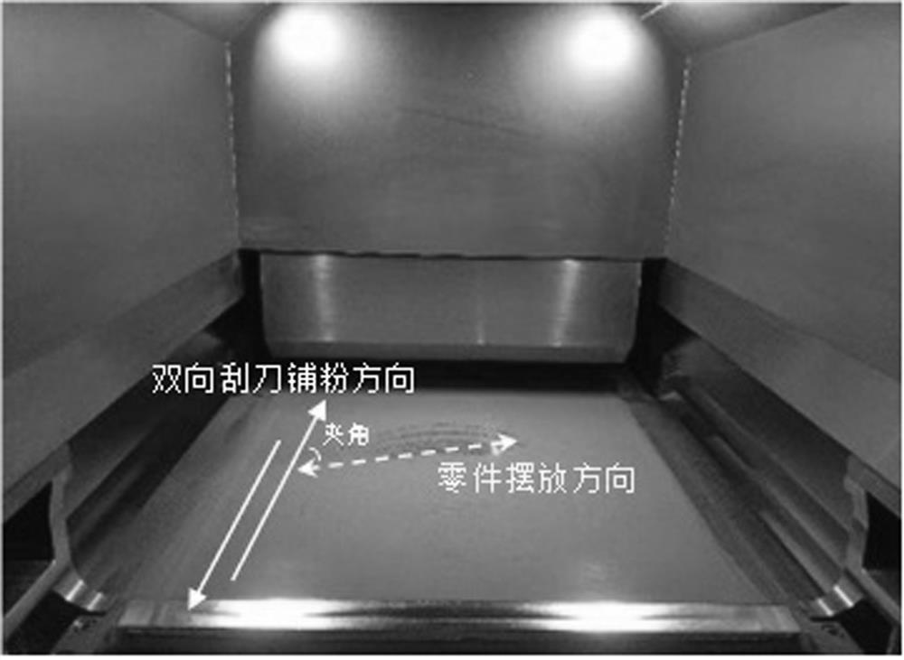
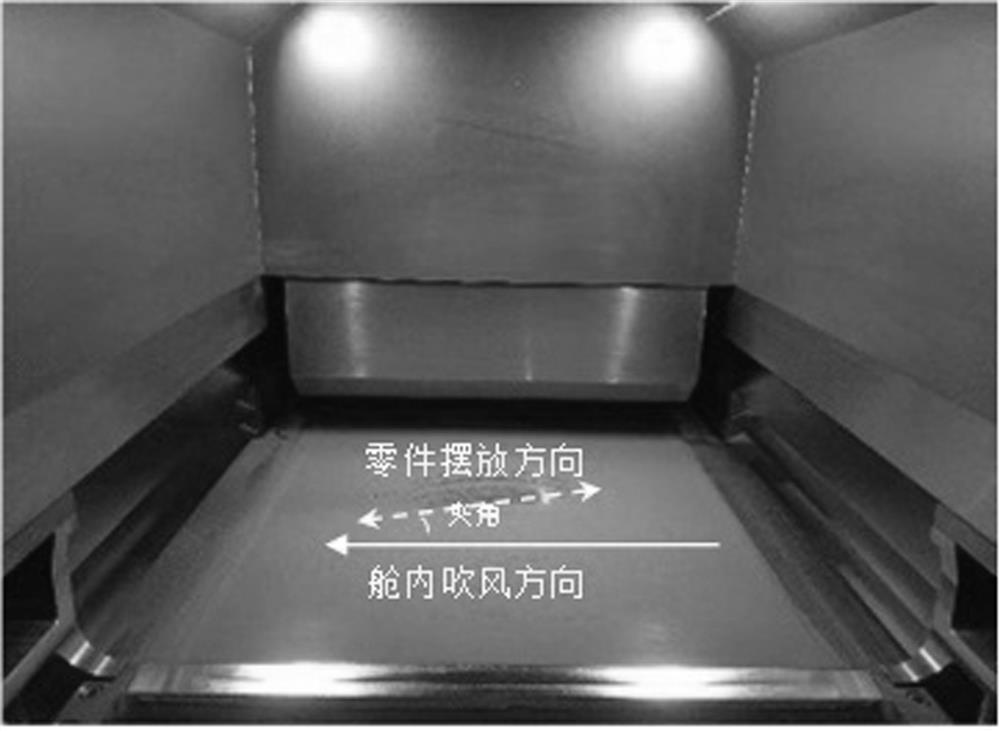
[0036] On the basis of the above embodiments, this embodiment further defines the position of the thin-walled metal member in the equipment forming cabin. The structural diagram of the 3D printing equipment forming cabin is as follows figure 1 As shown, in the step (1), the specific process of adjusting the position of the thin-walled metal component in the forming cabin of the equipment is as follows: keep the component as far away from the edge area of ​​the substrate as possible, and reduce the printing height of the component in the cabin as much as possible. The pre-processing digital model adjusts its forming position in the cabin, so that the forming area is as far away from the edge area of ​​the substrate as possible. The heat dissipation in the edge area of ​​the substrate is slow, and the stability of laser energy input is poor. Therefore, staying away from the edge area is beneficial to ensure the quality of components. Reduces the risk of warping.

[0037] As ment...


PUM


Abstract

The invention discloses a method for improving the success rate of 3D printing thin-walled metal components, which includes the following steps: 1) performing early software processing on the digital model of the thin-walled metal components, adjusting the position of the thin-walled metal components in the equipment forming cabin, ensuring Thin-walled metal components can be printed; 2) Place and optimize the digital models of thin-walled metal components that meet the above requirements; 3D printing equipment, preparatory work for printing equipment in the early stage, and start printing through 3D printing technology after the preparation work is completed; 4) After printing is completed, take out the thin-walled metal components for subsequent processing, and finally complete the delivery of thin-walled metal components. The present invention can give full play to the printing size correction function of the scraper through the secondary optimization of the placement position of the thin-walled metal components required by the basic placement, reduce the risk of scraper jamming, and improve the printing success rate of the thin-walled metal components.

Description

technical field [0001] The invention relates to the technical field of laser advanced additive manufacturing, and specifically refers to a method for improving the success rate of 3D printing thin-walled metal components. Background technique [0002] The additive manufacturing process (commonly known as 3D printing) is widely used in aviation, aerospace, etc. due to its advantages of high flexibility, short process, integrated forming of complex structures, small heat-affected area, high material utilization rate, high degree of freedom of operation, no pollution, and net shape. The field of manufacturing complex metal components has been applied on a large scale. [0003] However, with the continuous improvement of design-manufacturing requirements, the requirements for ultra-fine and complex structural components manufactured by additive manufacturing processes have also increased. In particular, there is an increasing demand for 3D printing of thin-walled metal componen...

Claims


Application Information

Patent Timeline
Patent Type & Authority Patents(China)
IPC IPC(8): B22F10/28B33Y10/00B33Y50/02B33Y80/00B33Y70/00
CPCB33Y10/00B33Y50/02B33Y80/00B33Y70/00B22F10/00B22F10/28B22F12/67Y02P10/25
Inventor 虞文军荣鹏王大为王东晔高川云朱振新
Owner CHENGDU AIRCRAFT INDUSTRY GROUP
Learn More