Material pressing assembly of side punching head

A technology of side-punching punches and components, which is applied in the field of die stamping, and can solve problems such as the inability to arrange the binder surface, punching backwards, and burrs

Pending Publication Date: 2020-06-16
SAIC-GM-WULING AUTOMOBILE CO LTD
View PDF0 Cites 1 Cited by
  • Summary
  • Abstract
  • Description
  • Claims
  • Application Information

AI Technical Summary

Problems solved by technology

However, the side punching action is usually assisted by a wedge mechanism. When the internal guide plate assembly of the wedge is worn or the V-shaped guide plate of the upper and lower molds is insufficiently ground, it is easy to cause fluctuations in the punching gap and one-sided cutting, causing punching to pull back or produce burrs
[0004] There are also some technologies that point out that the pressing surface is arranged on the edge of the punching position to ensure that the sheet is compacted before and during the punching process. However, during the daily operation of the mold, it is often necessary to perform mold maintenance or repair operations. When the punch support surface Due to grinding or when the binder surface is worn, it is easy to cause the binder surface to fail to effectively compact the sheet
In addition, for wedge punching with a negative angle, the binder surface cannot be arranged
[0005] There are also technologies that point out that polyurethane is fixed on the top of the punch on the side of the mold, and the pressing effect in the punching process is realized through polyurethane. However, polyurethane is a kind of polymer rubber material, which is prone to wear and tear under the reciprocating punching of the punch. Frequent inspection and replacement are required, which affects the quality and efficiency output of the workshop

Method used


Image

  • Material pressing assembly of side punching head
  • Material pressing assembly of side punching head
  • Material pressing assembly of side punching head

Examples


Embodiment Construction

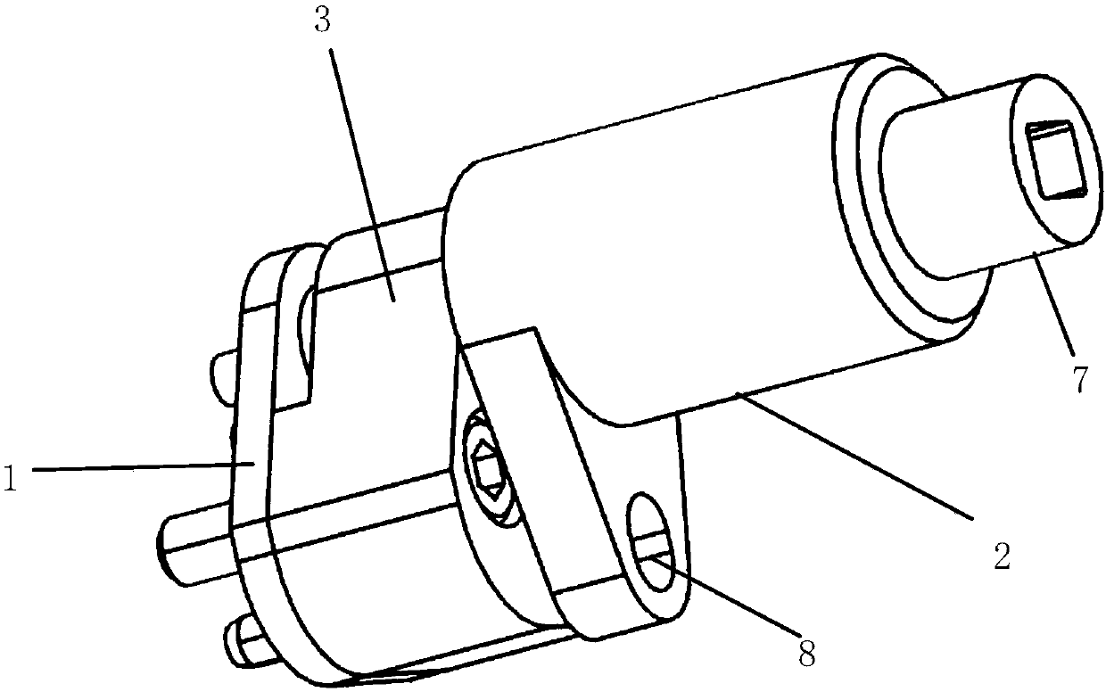
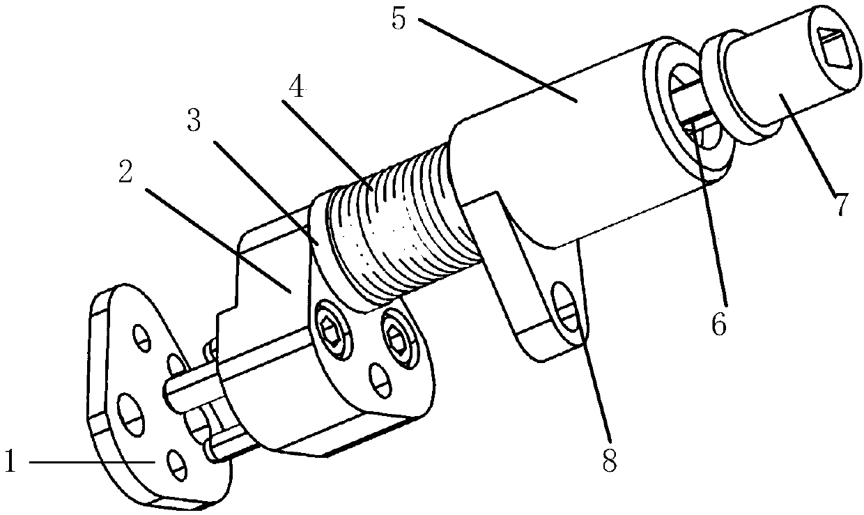
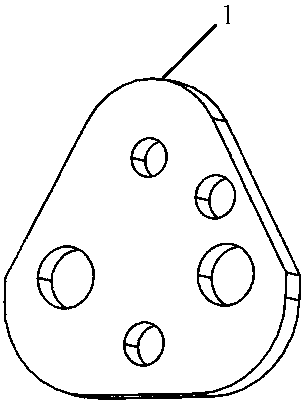
[0036] The following with attached Figure 1-12 The pressing assembly of a side punch punch of the present invention will be further described in detail.

[0037] For a pressing assembly of a side punch punch according to the present invention, please refer to Figure 1-12 , including a fixing device, a supporting device and an elastically stretchable pressing device, the supporting device is detachably fixed on the front end of the fixing device, the rear end of the fixing device is detachably fixed on the punching wedge, the The pressing device is elastically connected to the supporting device, the pressing device is elastically and movably connected in the supporting device along the axial direction, and the front end of the pressing device is releasably offset against the parts. In this way, when parts are punched and set, at first the pressing device of the present invention is installed on the punching wedge. When side punching, the pressing device is squeezed and comp...


PUM


Abstract

The invention discloses a material pressing assembly of a side punching head. The material pressing assembly comprises a fixing device, a supporting device and an elastically telescopic material pressing device, wherein the supporting device is detachably fixed to the front end of the fixing device, the rear end of the fixing device is detachably fixed to a punching wedge, the material pressing device is elastically connected into the supporting device, the material pressing device is elastically and movably connected into the supporting device in the axial direction, and the front end face ofthe material pressing device abuts against a part in a detachable mode. The material pressing assembly of the side punching head is simple in structure and convenient to disassemble and assemble, daily maintenance of a die can be facilitated, effective material pressing in the punching process is achieved, the punching quality is ensured, and the problem that a material pressing face is difficultto arrange can be effectively solved.

Description

technical field [0001] The invention relates to the technical field of die stamping, in particular to a pressing component of a side punch. Background technique [0002] In order to meet the diversified needs of the modern society for vehicle aesthetics and the transformation of automobile manufacturing to intelligence, higher requirements are put forward for cold stamping dies for automobile panels. When the traditional cold stamping die is used for side punching, especially for the punching mechanism with movable wedges for the lower die, the clamping plate usually cannot effectively compact the punching edge sheet, and the punching press is not solid enough to cause the punching to pull back or produce Burrs affect the quality of stamped sheet metal. [0003] Aiming at the problem of side punching or burrs caused by the inaccurate pressing of the binder plate, the existing technology proposes to modify the punch edge gap to make the side punch gap and the cutting edge am...

Claims


Application Information

Patent Timeline
Patent Type & Authority Applications(China)
IPC IPC(8): B21D28/34
CPCB21D28/34
Inventor 韦荣发蒙世瑛黄棋
Owner SAIC-GM-WULING AUTOMOBILE CO LTD
Why Eureka
Try Eureka