An automatic control system for releasing foil in the production of electrode foil

An automatic control system and electrode foil technology, applied in general control systems, control/regulation systems, electrical program control, etc., can solve problems such as shortening the service life of equipment, hidden dangers, and inaccurate surface tension of foil surfaces, and achieve per capita work. The effect of improving efficiency, ensuring operational safety, and ensuring operational safety

Active Publication Date: 2020-12-22
NANTONG HAIXING ELECTRONICS +2
View PDF6 Cites 0 Cited by
  • Summary
  • Abstract
  • Description
  • Claims
  • Application Information

AI Technical Summary

Problems solved by technology

The traditional foil release mechanism needs to manually control the falling time, distance and length of the foil release mechanism, and the foil release delay transmission roller group is in free fall during the falling process, which will cause the surface tension of the foil surface to be out of alignment. cause product loss
[0003] Compared with the current production technology, the current shortcomings are as follows: 1. Human control of the operating parameters of the foil release mechanism has high technical requirements for operators, which is not conducive to human-computer interaction; 2. Multiple people are required to cooperate to complete the foil change process , the per capita work efficiency is extremely low, which is not conducive to the automatic production of the production line; 3. The free fall of the foil release mechanism causes a large product loss and shortens the service life of the equipment; 4. Artificial control of the foil release mechanism requires high-altitude operations , causing safety hazards

Method used


Image

  • An automatic control system for releasing foil in the production of electrode foil
  • An automatic control system for releasing foil in the production of electrode foil
  • An automatic control system for releasing foil in the production of electrode foil

Examples


Embodiment approach

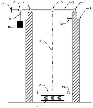
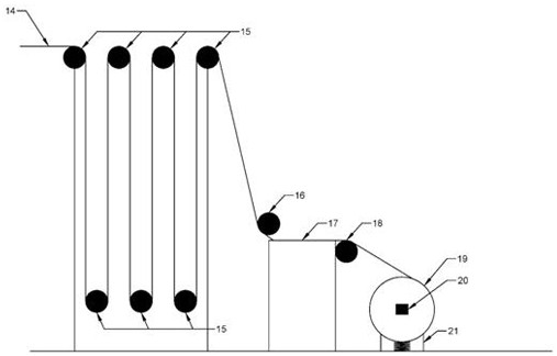
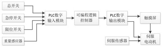
[0019] like figure 1 , figure 2 , image 3 , Figure 4 An embodiment of an automatic foil releasing control system in electrode foil production is shown, including a foil releasing device, a foil connecting device, a PLC control module, and a servo control module. The foil release device consists of a frame 1, a metal shaft 2, a delay rope reel 3, a bearing and a bearing seat 4, a foil release delay traction rope 5, a foil release delay transmission roller group 6, a spring protection bracket 7, and a Heavy rope reel 8, counterweight traction rope 9, counterweight 10, turntable 11, upper limit switch 12 and lower limit switch 13, the metal shaft 2 is used to connect delay rope reel 3, bearing and bearing seat 4. The counterweight rope reel 8 and the turntable 11, the bearing and the bearing seat 4, the upper limit switch 12 and the lower limit switch 13 are all installed on the frame 1, and the delay rope reel 3 and the foil release delay The transmission roller group 6 i...


PUM


Abstract

The invention discloses an automatic foil releasing control system in electrode foil production. The system comprises a foil placing device, a foil receiving device, a PLC control module and a servo control module, the foil releasing device is composed of a machine frame, a metal rotating shaft, a delay rope winder, a bearing, a bearing pedestal, a foil releasing delay traction rope, a foil releasing delay transmission roller set, a spring protection support, a balance weight rope winder, a balance weight traction rope, a balance weight block, a rotating disc, an upper limiting switch and a lower limiting switch. The foil receiving device is composed of a brake roller, a foil receiving platform, a foil unwinding roller, an electrode foil roll, a servo control module and a weight sensor. The automatic foil releasing control system has the following advantages that through PLC and servo control, the foil releasing tension is dynamically adjusted, and the product loss is reduced; and thefoil placing process is controlled in a full-automatic mode, system parameters are set through a touch screen, man-machine interaction is improved, and per capita production efficiency is improved.

Description

technical field [0001] The invention relates to an automatic foil releasing control system in electrode foil production. Background technique [0002] As an important energy storage component of capacitors, electrode foil is widely used in various capacitor products. Electrode foil has two production processes, namely corrosion and chemical formation. The corroded raw material is aluminum foil, the aluminum foil becomes the corroded foil after the corroding process, and the corroded foil becomes the electrode foil after the chemical forming process. In corrosion and chemical conversion production, raw materials are stored in units of "rolls". Therefore, in order to ensure the continuity of production, after the production of the current production foil roll is completed, the foil connection operation will be artificially carried out, that is, the new foil roll will be connected with the previous one. The foil rolls are joined by riveting. The foil connection operation usu...

Claims


Application Information

Patent Timeline
Patent Type & Authority Patents(China)
IPC IPC(8): G05B19/05
CPCG05B19/054G05B2219/13099
Inventor 陈晨
Owner NANTONG HAIXING ELECTRONICS
Why Eureka
Try Eureka