Pressure vessel manufacturing method and auxiliary manufacturing equipment thereof

A pressure vessel and auxiliary manufacturing technology, applied in chemical instruments and methods, manufacturing tools, metal processing equipment, etc., can solve the problems of reduced grinding efficiency, insufficient grinding transition grinding, and inability to control the degree of grinding, so as to improve grinding efficiency. Effect

Inactive Publication Date: 2022-03-15
浙江九树机械有限公司
View PDF1 Cites 0 Cited by
  • Summary
  • Abstract
  • Description
  • Claims
  • Application Information

AI Technical Summary

Problems solved by technology

[0006] However, there are still many problems in the above-mentioned patent: 1. The above-mentioned grinding device collects punctuation points through the image acquisition device during the grinding process and cooperates with the lifting mechanism and the rotary mechanism to position and polish the weld seam. However, this grinding method cannot control the grinding. Second, the above-mentioned grinding device will spray the rust remover through the transparent cover and the atomizing nozzle to prevent the flying dust generated by the grinding, but when the rust remover is sprayed, it still needs to be strengthened; The dosage of the rust remover was not adjusted at the time, which may easily lead to insufficient or excessive dosage, resulting in reduced grinding efficiency

Method used


Image

  • Pressure vessel manufacturing method and auxiliary manufacturing equipment thereof
  • Pressure vessel manufacturing method and auxiliary manufacturing equipment thereof
  • Pressure vessel manufacturing method and auxiliary manufacturing equipment thereof

Examples


Embodiment 1

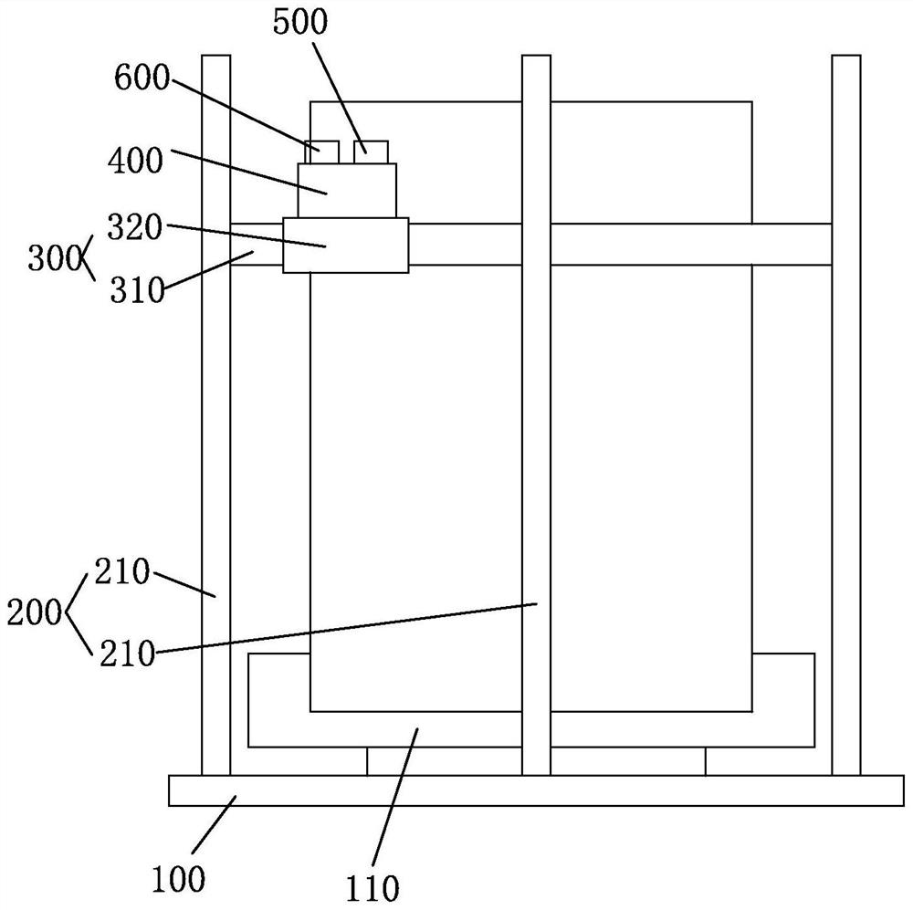
[0039] Such as figure 1 As shown, the embodiment of the present application provides an auxiliary manufacturing equipment for pressure vessels. The auxiliary manufacturing equipment includes: a base 100 for placing a pressure vessel, and a rotating disk 110 is provided on the base 100, and the pressure vessel is placed on the rotating disk 110. The rotating disk 110 drives the pressure vessel to rotate; the lifting device 200 is arranged on the base 100, and the lifting device 200 includes a plurality of vertically arranged lifting rods 210 surrounding the periphery of the pressure vessel; the surrounding device 300 is arranged on the lifting rod 210, and the surrounding device 300 includes a fixed ring 310 and a sliding block 320 arranged on the fixed ring 310. The sliding block 320 moves circularly around the pressure vessel along the fixed ring 310. The fixed ring 310 moves up and down along the pressure vessel through the lifting device 200; the grinding device 400 is set ...

Embodiment 2

[0042] The embodiment of the present application provides a pressure vessel manufacturing method and its auxiliary manufacturing equipment. In addition to the above technical features, the pressure vessel manufacturing method and its auxiliary manufacturing equipment in the embodiment of the present application also include the following technical features.

[0043] As shown in the figure, the grinding device 400 includes: a grinding base 100, which is installed on the sliding block 320; a driver 420, which is arranged on the grinding base 100, and the end of the driver 420 is provided with a grinding head 421, and the driver 420 drives the grinding head 421 to rotate, The grinding head 421 is used for grinding the pressure vessel; the protective cover 430 is arranged on the outside of the grinding head 421 to prevent the dust from splashing during grinding, and one end of the protective cover 430 is connected to the grinding base 100; the collecting device 440 is arranged on th...

Embodiment 3

[0046] The embodiment of the present application provides a pressure vessel manufacturing method and its auxiliary manufacturing equipment. In addition to the above technical features, the pressure vessel manufacturing method and its auxiliary manufacturing equipment in the embodiment of the present application also include the following technical features.

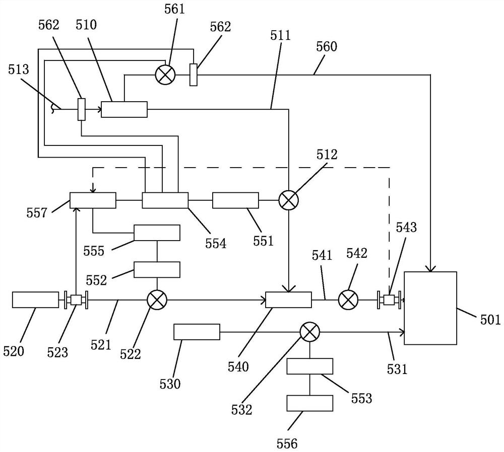
[0047] As shown in the figure, the spraying device 500 includes: a sprayer 501 disposed on the protective cover 430 for spraying liquid, one end of the sprayer 501 penetrates the protective cover 430 and extends into the protective cover 430; a first liquid storage tank 510, Placed on the ground for storing water, and the first liquid storage tank 510 is connected to the tap water pipe 513; the second liquid storage tank 520 is set on one side of the first liquid storage tank 510 for storing rust removal liquid; the third The liquid storage tank 530 is arranged on one side of the second liquid storage tank 520 for storing ...


PUM


Abstract

The invention discloses auxiliary manufacturing equipment for a pressure container, and the equipment comprises a base which is used for placing the pressure container and is provided with a rotating disc, the pressure container is placed on the rotating disc, and the rotating disc drives the pressure container to rotate; the lifting device is arranged on the base, and the lifting device comprises a plurality of lifting rods which surround the periphery of the pressure container and are vertically arranged; the surrounding device is arranged on the lifting rod, the surrounding device comprises a fixing ring and a sliding block arranged on the fixing ring, the sliding block annularly moves along the fixed surrounding pressure container, and the fixing ring ascends and descends along the pressure container through the lifting device; the grinding device is arranged on the sliding block and used for grinding the pressure container, and the grinding device does annular motion along the pressure container through a surrounding device; and the spraying device is arranged on the sliding block and used for spraying rust removal liquid.

Description

technical field [0001] The invention belongs to the technical field of pressure vessels, and in particular relates to a pressure vessel manufacturing method and auxiliary manufacturing equipment thereof. Background technique [0002] A pressure vessel refers to a closed device that contains gas or liquid and bears a certain pressure. In order to more effectively implement scientific management and safety supervision and inspection, my country's "Pressure Vessel Safety Supervision Regulations" divides pressure vessels into three categories according to working pressure, medium hazards and their role in production. [0003] A pressure vessel is a closed container that can withstand pressure. The pressure vessel has a wide range of uses, and it has an important position and role in many sectors such as industry, civil, military, and many fields of scientific research. Among them, the most used ones are in the chemical industry and the petrochemical industry, and the pressure ...

Claims


Application Information

Patent Timeline
Patent Type & Authority Applications(China)
IPC IPC(8): B24B9/04B24B49/12B24B41/06B24B55/06B24B55/12B24B41/02B24B51/00B24B1/00C23G3/00B01F35/22B01F35/71B01F35/80
CPCB24B9/04B24B49/12B24B41/06B24B55/06B24B55/12B24B41/02B24B51/00B24B1/00C23G3/00
Inventor 卢凯园黄志方吕云建梅霖洪王毅鑫
Owner 浙江九树机械有限公司
Why Eureka
Try Eureka