
Micro-channel evaporator and control method thereof

An evaporator and micro-channel technology, applied in evaporators/condensers, refrigerators, refrigeration components, etc., can solve the problem of reduced heat transfer capacity of micro-channel evaporators, reduced heat transfer capacity of second-row heat exchangers, and impact on Rear row heat exchanger heat exchange and other issues, to achieve the effect of benefiting performance, reducing pressure drop, and strong frosting ability

Active Publication Date: 2020-06-05
XI AN JIAOTONG UNIV
View PDF11 Cites 4 Cited by
  • Summary
  • Abstract
  • Description
  • Claims
  • Application Information

AI Technical Summary

Problems solved by technology

[0003] Conventional two-row micro-channel evaporator, when working under frosting conditions, there is a phenomenon that the front heat exchanger frosts faster, and the frost will block the air duct, affecting the heat transfer of the rear heat exchanger , this is because the front heat exchanger is on the windward side, and the water vapor in the air condenses on the front heat exchanger first, resulting in faster frosting of the front heat exchanger, and the heat exchange capacity of the second heat exchanger is reduced. will be reduced, thereby reducing the heat transfer capacity of the entire microchannel evaporator

Method used


Image

  • Micro-channel evaporator and control method thereof
  • Micro-channel evaporator and control method thereof
  • Micro-channel evaporator and control method thereof

Examples


Embodiment Construction

[0018] The specific implementation manners of the present invention will be described in detail below in conjunction with the accompanying drawings.

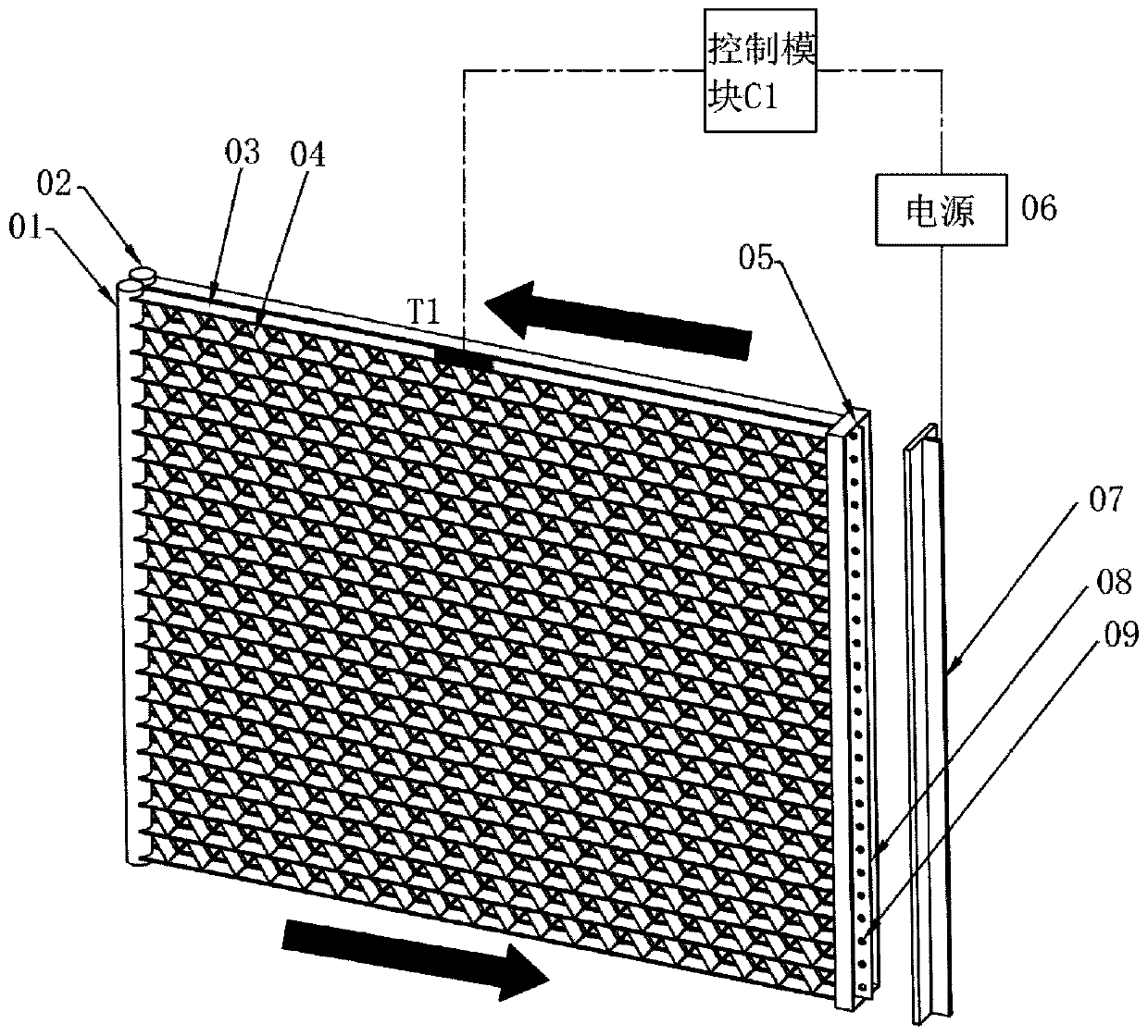
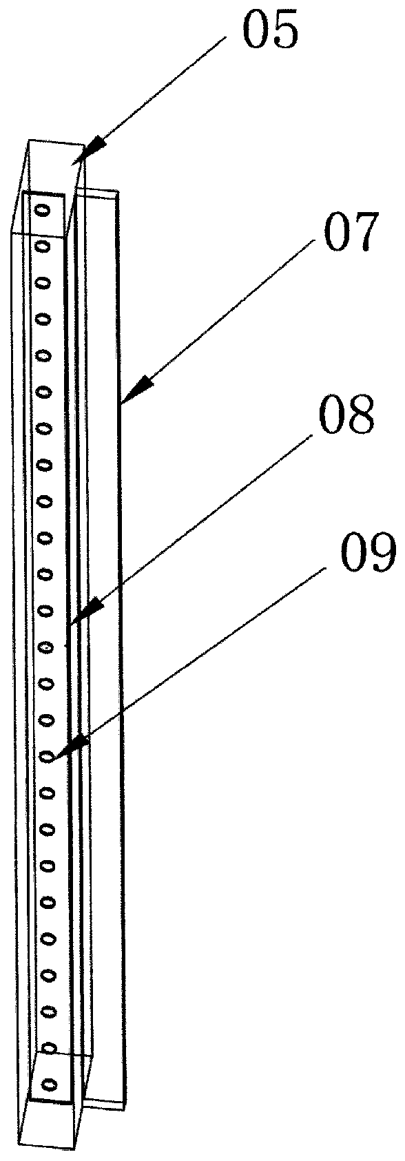
[0019] like figure 1 and figure 2 As shown, a microchannel evaporator of the present invention includes a first liquid collection pipe 01 and a second liquid collection pipe 02 arranged side by side, and a third liquid collection pipe on the opposite side of the first liquid collection pipe 01 and the second liquid collection pipe 02 The liquid collection pipe 05 is arranged between the first liquid collection pipe 01 and the third liquid collection pipe 05, the second liquid collection pipe 02 and the third liquid collection pipe 05 and communicates with the first liquid collection pipe 01 and the third liquid collection pipe 05. A plurality of flat tubes 03 of the second liquid collecting pipe 02 and the third liquid collecting pipe 05, the fins 04 installed between adjacent flat pipes, two rows of flat pipes 03 before and a...


PUM


Abstract

The invention discloses a micro-channel evaporator and a control method thereof. The micro-channel evaporator comprises three liquid collecting pipes, flat pipes, fins, an electromagnet, a power supply and a throttle plate, wherein the throttling plate is added in the middle of the third liquid collecting pipe, throttling holes are formed in the throttling plate, the throttling plate is made of amagnetic material, the third liquid collecting pipe is provided with a protruding channel, and the electromagnet is arranged in the protruding channel. According to the evaporator, when the micro-channel evaporator works under a frosting working condition, the power supply is powered on, and the throttling plate can throttle a refrigerant flowing from a front-row heat exchanger, so that the temperature of a rear-row heat exchanger of the micro-channel evaporator is lower, the frosting capacity of the rear-row heat exchanger is higher, frosting performs towards the rear-row heat exchanger, uniform frosting of the micro-channel evaporator is achieved, and the performance of the micro-channel evaporator under the frosting working condition is improved; and when the micro-channel heat exchangeevaporator works under a non-frosting working condition, the power supply is cut off, and the throttling plate does not play a throttling role at the moment, so that the resistance of the micro-channel evaporator is reduced, and the improvement of the energy efficiency of the micro-channel evaporator is facilitated.

Description

technical field [0001] The invention relates to the technical field of microchannel evaporators, in particular to a microchannel evaporator and a control method thereof. Background technique [0002] Microchannel heat exchangers have the advantages of high heat transfer efficiency, small size, compact structure, small refrigerant charge, and low production cost. They have been used as condensers in refrigeration systems on a large scale, especially in automotive air conditioners. It has been widely used. Due to the widespread application of air source heat pumps in recent years, microchannel heat exchangers have great advantages as a compact heat exchanger and can replace finned tube heat exchangers as air source heat pumps. Evaporator. [0003] Conventional two-row micro-channel evaporator, when working under frosting conditions, there is a phenomenon that the front heat exchanger frosts faster, and the frost will block the air duct, affecting the heat transfer of the rear...

Claims


Application Information

Patent Timeline
IPC IPC(8): F25B39/02F25B41/06F25B47/00F25B49/00F28F9/02F25B41/30
CPCF25B39/02F25B47/00F25B49/00F28F9/02F25B41/30
Inventor 熊通晏刚鱼剑琳樊超超
Owner XI AN JIAOTONG UNIV
Learn More