
A serrated electrode and a method for improving the performance of nano-ultraviolet detectors

A UV detector, sawtooth technology, applied in the direction of electric solid devices, circuits, electrical components, etc., can solve the problems of incompatibility between the performance of metal electrodes and process steps

Active Publication Date: 2021-12-10
BEIJING UNIV OF TECH
View PDF5 Cites 0 Cited by
  • Summary
  • Abstract
  • Description
  • Claims
  • Application Information

AI Technical Summary

Problems solved by technology

[0003] The purpose of the present invention is to provide a sawtooth electrode and a method for improving the performance of nano-ultraviolet detectors, which solves the problem of incompatibility between metal electrode performance and process steps

Method used


Image

  • A serrated electrode and a method for improving the performance of nano-ultraviolet detectors
  • A serrated electrode and a method for improving the performance of nano-ultraviolet detectors
  • A serrated electrode and a method for improving the performance of nano-ultraviolet detectors

Examples


Embodiment approach 1

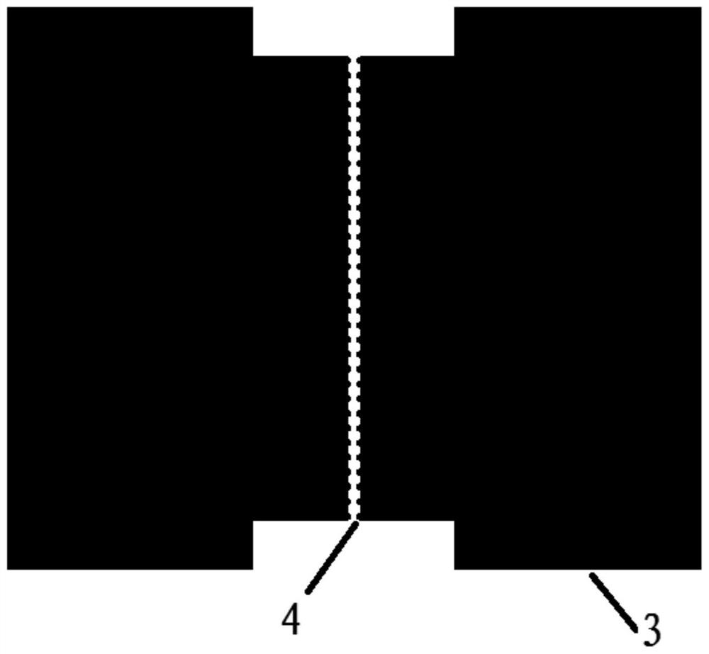
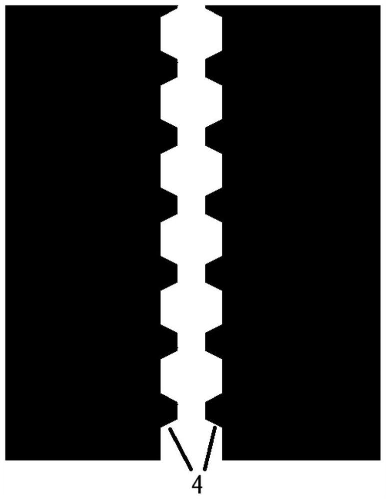
[0097] Using electron beam direct writing technology or laser direct writing technology, a photoresist plate is prepared according to the layout, and the shape of the layout is the shape of a sawtooth electrode.

[0098] SiO with a thickness of 300nm is oxidized on the surface of a silicon (Si) sheet by high temperature oxidation 2 layer, will have silicon dioxide (SiO 2 ) layer of Si sheet as electrode substrate, SiO 2 The layer is an insulating isolation layer.

[0099] First, wash the electrode substrate twice with acetone, then wash the electrode substrate twice with ethanol, and finally wash the electrode substrate twice with deionized water. Cover the photolithographic plate on the cleaned electrode substrate, and use ultraviolet lithography technology to photolithographically publish the pattern on the electrode substrate.

[0100] Use the radio frequency magnetron sputtering method to sputter a zinc oxide seed layer with a thickness of 95nm on the photolithographic ...

Embodiment approach 2

[0108] Using electron beam direct writing technology or laser direct writing technology, a photoresist plate is prepared according to the layout, and the shape of the layout is the shape of a sawtooth electrode.

[0109] SiO with a thickness of 300nm is oxidized on the surface of a silicon (Si) sheet by high temperature oxidation 2 layer, will have silicon dioxide (SiO 2 ) layer of Si sheet as electrode substrate, SiO 2 The layer is an insulating isolation layer.

[0110] First, wash the electrode substrate twice with acetone, then wash the electrode substrate twice with ethanol, and finally wash the electrode substrate twice with deionized water. Cover the photolithographic plate on the cleaned electrode substrate, and use ultraviolet lithography technology to photolithographically publish the pattern on the electrode substrate.

[0111] Use the radio frequency magnetron sputtering method to sputter a zinc oxide seed layer with a thickness of 115nm on the photolithographic l...


PUM

PropertyMeasurementUnit
lengthaaaaaaaaaa
lengthaaaaaaaaaa
thicknessaaaaaaaaaa

Abstract

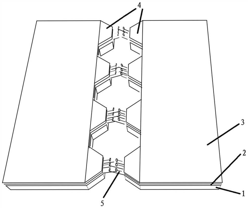
The invention discloses a serrated electrode and a method for improving the performance of a nano-ultraviolet detector, and relates to the technical field of semiconductors. The shape of the zigzag electrode is composed of two symmetrically arranged figures; the figure is composed of a rectangle and a plurality of isosceles trapezoids, the lower base of the isosceles trapezoid is connected with the same long side of the rectangle, and the opposite side of the two figures is One side where multiple isosceles trapezoids are located; the isosceles sides and upper bases of the isosceles trapezoids are used to grow nanowires; the nanowires grown on the upper bases of two symmetrical isosceles trapezoids on the opposite side of the two figures form a bridge. The opposite sides of the two figures of the zigzag electrode shape in the present invention are composed of multiple repeated isosceles trapezoids, and the nanowires grown on the seed layer of the zigzag electrodes only form effective bridges on the upper base of the isosceles trapezoids. After growing the nanowires There is no need to remove redundant nanowires, the number of nanowire bridges and process steps are reduced, and the response speed and light gain of the nano-ultraviolet detector are improved.

Description

technical field [0001] The invention relates to the technical field of semiconductors, in particular to a serrated electrode and a method for improving the performance of a nano-ultraviolet detector. Background technique [0002] Ultraviolet detectors are one of the indispensable devices in the fields of environmental monitoring, ultraviolet communication, life sciences, missile guidance, and early warning. The use of nanostructured materials can greatly improve the performance of devices. At present, most of the researches on UV detectors focus on the materials and properties of the detectors. Taking the third-generation wide-bandgap semiconductor material ZnO as an example, there has been research on the preparation of a single ZnO nanowire UV detector by depositing electronic contacts using electron beam lithography. Compared with the undoped MSM prepared by Wang Yi et al. Type zinc oxide thin film ultraviolet detector, the gain of a single ZnO nanowire ultraviolet dete...

Claims


Application Information

Patent Timeline
Patent Type & Authority Patents(China)
IPC IPC(8): H01L31/0224H01L31/108
CPCH01L31/022408H01L31/1085H01L31/0224H01L31/09H01L31/035227H01L31/1828H01L27/14601
Inventor 高志远陆利伟赵立欢邹德恕
Owner BEIJING UNIV OF TECH
Learn More