
FPGA-based range migration compensation system

A technology of distance migration and compensation system, applied in radio wave measurement systems, instruments, etc., can solve the problems of low real-time performance, low computational complexity, and large amount of computation, and achieves low occupation of logic resources, high compensation accuracy, Fast processing effects

Active Publication Date: 2020-06-02
SHANGHAI RADIO EQUIP RES INST
View PDF9 Cites 2 Cited by
  • Summary
  • Abstract
  • Description
  • Claims
  • Application Information

AI Technical Summary

Problems solved by technology

This method has low computational complexity but a large amount of calculation, and the real-time performance is not high.

Method used


Image

  • FPGA-based range migration compensation system
  • FPGA-based range migration compensation system
  • FPGA-based range migration compensation system

Examples


Embodiment Construction

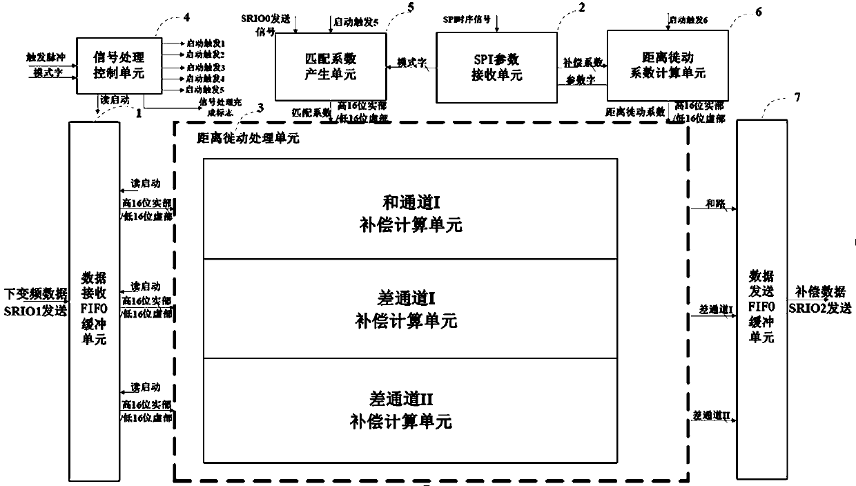
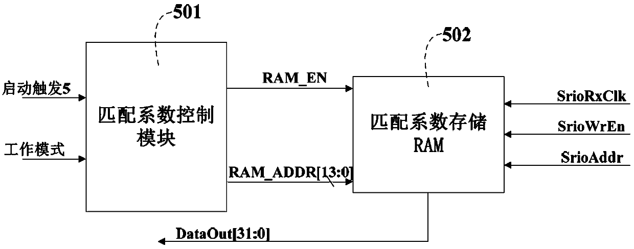
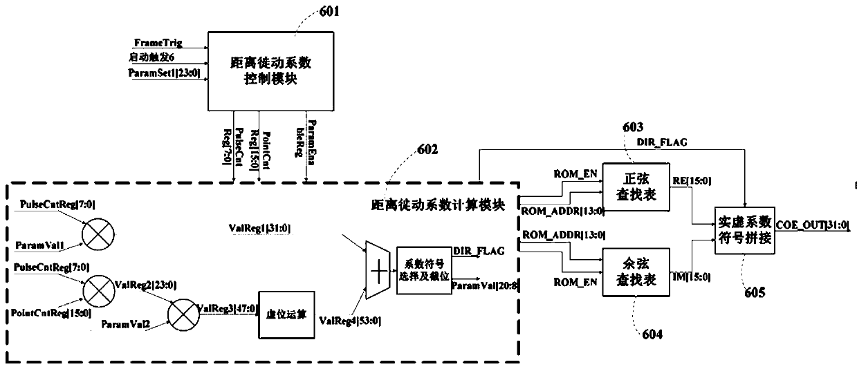
[0059] based on the following Figure 1 to Figure 5 , specifically explain the preferred embodiment of the present invention.

[0060] The distance migration compensation system provided by the present invention is realized through software programming based on the FPGA hardware platform. In one embodiment of the present invention, the distance migration compensation system is realized by programming the FPGA hardware platform Kintex_7.

[0061] Such as figure 1 As shown, a kind of FPGA-based distance migration compensation system provided by the present invention specifically includes:

[0062] The data receiving FIFO buffer unit 1 is used to receive the three-way orthogonal IQ data after the active radar digital down-conversion preprocessing by means of ping-pong buffering;

[0063] The SPI parameter receiving unit 2 is used to calculate the working mode and compensation coefficient according to the parameters of the missile-borne platform;

[0064] The matching coefficie...


PUM


Abstract

The invention discloses an FPGA-based range migration compensation system. According to the present invention, the guidance radar signal preprocessing is used for the phase-coherent accumulation and target detection of a subsequent CPU through the processes of frequency domain transformation, matching complex multiplication, migration frequency domain compensation, time domain transformation, fixed-point floating point conversion and the like in an FPGA. The system solves the problem of range migration caused by the high missile-borne motion speed and high radar resolution, realizes the inter-pulse envelope alignment compensation of the low repetition frequency radar within extremely short time, improves the signal-to-noise ratio of the radar signal accumulation, and has better real-time performance and transportability.

Description

technical field [0001] The invention relates to the technical field of microwave radar detection, in particular to an FPGA design method for high-precision compensation of energy loss caused by distance migration of radar echoes applied to missile-borne high-speed motion platforms. Background technique [0002] The traditional guidance radar belongs to the detection sensor of the high-speed moving platform. In order to have good adaptability to the moving platform and obtain a longer detection distance and a higher distance resolution capability, the linear frequency modulation (LFM) signal is usually used as the radar transmission signal. The emission not only has a wider pulse width, but also has a larger signal bandwidth. The echo signal adopts pulse compression technology, and after matched filtering, a larger time-width-bandwidth product can be obtained, which improves the distance resolution ability of the target. [0003] In order to detect low RCS targets on a high-...

Claims


Application Information

Patent Timeline
Patent Type & Authority Applications(China)
IPC IPC(8): G01S7/41G01S7/02
CPCG01S7/41G01S7/02
Inventor 许彦章蒋洁李伯达姜艳娜张天键
Owner SHANGHAI RADIO EQUIP RES INST
Learn More